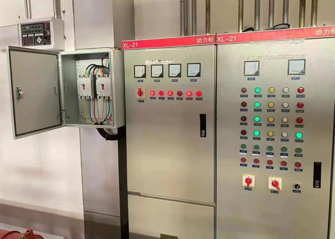
A board with built-in surge arresters carries three devices, not one. Protection sits at the intake, on every floor board and at the load. Each unit handles what the level above let through. Ask low voltage switchgear manufacturers for one drawing that shows all three.
Key Takeaways
- Three levels, one chain: an arrester at the intake alone leaves everything downstream exposed.
- The class follows the position. Type 1 at the intake, Type 2 on the floor board, Type 3 at the load.
- Conductor length beats brand: a long earth lead wastes the device you already paid for.
- Ask for the mounting drawing: a catalogue page proves nothing about what fits in the enclosure.
- One party should own the coordination: split responsibility is where the numbers stop adding up.
Surge arresters sit at three levels of one distribution chain
The three units are not interchangeable. A device sized for the intake will not protect a control panel thirty metres away. A terminal module would not survive the intake.
In low voltage distribution those points are the incoming section, the floor board and the final circuit. Plenty of buyers place one device at the intake and assume the rest is covered. It is not.
A 25 kA impulse arriving at the intake can still reach a floor board as 2 to 3 kA. The floor board sees the remainder. The load end sees what is left after that.
The incoming level: where an arrester belongs inside the incoming section
At the intake, fit the arrester on the supply side of the main device. Give it its own compartment or a dedicated rail. Run the shortest possible conductor to the main earth bar.
Position matters more than rating here. A device wired downstream of the main breaker lets the impulse pass through the breaker first. A distribution switchboard built this way protects the installation and not the switch itself.
This is the level that decides which supplier you are really buying from. A low voltage switchgear manufacturer builds the intake section, so the arrester is on their drawing or nowhere. Buyers who shop for an electrical power distribution panel as a finished box often find that decision already made.
The floor level: matching an arrester to a distribution panelboard
A distribution panelboard on a floor plate needs a Type 2 device. It handles the let-through from the intake and brings the residual voltage down to something equipment survives.
Type 2 units mount on the same rail as the outgoing devices. That is where space runs out first. Nobody reserves a slot until an arrester is ordered.
| Level | Class | Where it mounts | Who normally supplies it |
|---|---|---|---|
| Intake | Type 1 | Supply side of the main device, in its own compartment | The builder of the incoming section |
| Floor board | Type 2 | Dedicated rail beside the incomer | The board supplier, on their own layout drawing |
| Load end | Type 3 | Inside the final enclosure, next to the protected equipment | The board supplier, or the vendor of the driven equipment |
| Interface between two suppliers | Not a device | In the coordination note, as a residual voltage figure | The party owning the level above, who sets the let-through |

The rail the arrester has to share
The outgoing devices take the rail first. A floor board drawing that hides the rail behind a device list tells you nothing about whether a module fits.
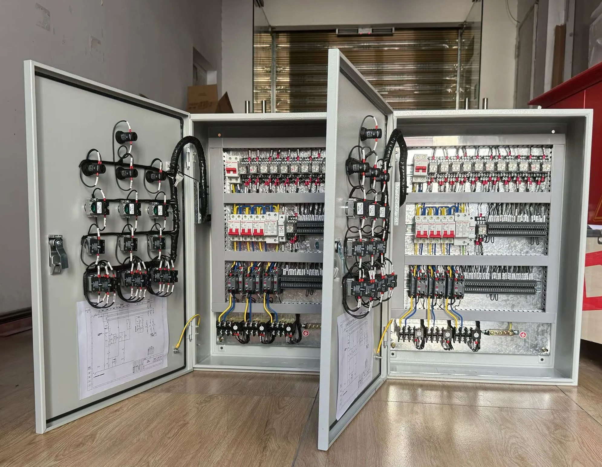
Ask for a photograph of the internal arrangement before you order. Spacing, labelling and the distance to the earth bar are visible in a photograph, and missing from a catalogue drawing.
The load end: a Type 3 device beside the final circuits
Type 3 protection sits next to what it protects: a control panel, a drive, an instrument supply. It lives in the smallest enclosure in the chain, usually a distribution electrical box or an electrical distribution box.
This is the level that fails first, and the reason is usually the earth reference. A Type 3 module bonded to a different bar from the equipment it serves protects nothing at all.
Order it with the board, not later. A module bought after handover rarely gets the short conductor and the reserved rail position it needs. On an electric distribution box fed from a long cable run, that shortfall shows up as a failed drive.

Two conductors, numbered, back to the same bar
A Type 3 device needs its own live and earth conductors, ferruled and recorded on the drawing. Borrowing a terminal from the circuit it guards defeats the purpose.
This is where a good installation and a cheap one look most different. Both have a module. Only one has the routing to make it work.
What separates a built-in arrester from a bolted-on module
Look for the module on the board drawing. It needs its own compartment or rail, and a busbar connection instead of a loop of wire. It also needs a disconnector and a volt-free status contact.
The power distribution boards in a switch room are sized once. If the enclosure is not sized around those four items, the fitter invents a bracket and calls it protected.
Heat is the other constraint. A sealed pocket shared with the outgoing devices raises the temperature the cartridge sits at. A warm module ages faster than its datasheet suggests.
Reading a supplier offer for the lines that decide it
Four lines separate a supplier who builds arresters in from one who resells modules. Ask for the mounting drawing, the coordination note and the device certificate. On a power distribution enclosure that drawing is the only proof the module was designed in.
| Offer line | What to ask for | Why it decides the outcome |
|---|---|---|
| Class and position | The class, the mounting point and the backup device rating | A class without a position cannot be checked against your schedule |
| Conductor to the earth bar | Total length in millimetres, live and earth sides together | Every extra centimetre adds inductive drop at the terminals |
| Disconnector and status contact | Whether the module isolates on its own and reports its state | A spent cartridge looks identical to a healthy one on the rail |
| Test evidence | The routine report for your serial number and the certificates | A type test covers the build, not the unit that left the works |
The enclosure assembly still has to satisfy IEC 61439. The cartridge inside it is covered by the device certificate, not by the assembly test.
Check the quality system too. A builder certified to ISO 9001 keeps the routine test record as process, not as a favour. That record is what an inspector asks for after an event.
Coordinating the three levels before the load sees anything
The three devices only work as a chain when each one survives what the level above passes down. That is an energy question. It has to be answered on paper before ordering.
Long overhead spurs are common on flow stations in the Niger Delta and on mine sites in the Copper Belt. Electrification across Sub-Saharan Africa keeps adding exposed overhead routes, according to the IEA. Each new spur is another path an impulse can take into a board.
Ask each bidder for the residual voltage at every level they supply. If two suppliers own two levels, neither can state the handover figure. Buy from low voltage switchgear manufacturers that quote all three levels.

Four documents a real arrester supplier already has
Frequently asked questions
Which suppliers provide distribution boards with built-in surge arresters?
Does an arrester at the intake remove the need for one on each floor board?
What class of arrester does a main distribution switchboard need?
Can an arrester be added to a board after it has been built?
How long can the conductor from the arrester to the earth bar be?
Is a Type 3 device worth fitting if the floor board already has a Type 2 unit?
How do I compare two suppliers offering the same arrester class?
Does a distribution panelboard need a separate earth bar for the arrester?
Final thoughts
Built-in means three devices on one drawing, one earth reference and one party accountable for the residual numbers. Send your incoming arrangement, the floor board schedule and the loads you cannot lose. Giantele returns a layout with an arrester at every level.
Specifying arresters across three levels?
Send the incoming supply arrangement, the floor board schedule and your sensitive loads. Giantele engineers return a marked layout and a technical proposal covering every level.