
Key Takeaways
- Arc resistance is a test result, not a property of the steel.
- The claim holds for one current, one duration and the faces that were tested.
- Most of the energy leaves as hot gas, and the room decides where it goes.
- Your fault level picks the report you need, not the biggest one on offer.
- Insist on the report page, the relief drawing and the label, in that order.
Arc resistance is a test result, not a material
Arc-resistant motor control centres are sold on the strength of one document. That document records what happened in a test cell, on one day, to one assembly. It says nothing about the steel, and it does not travel with the design.
A motor control center manufacturer can only claim what a test house has signed. The signature covers a stated current, a stated time and a stated set of closed or open faces.
Change any one of those three and the claim drops away. Sellers rarely volunteer that, because the phrase sounds absolute. It is not absolute. It is a condition with three variables.
The assembly standard behind the build is IEC 61439. It covers design verification and a routine test on every unit. Internal arc testing is a separate exercise. It produces the pages buyers actually want to read.
Ask control panel manufacturers for the report page and the conversation changes. The ones who test keep a copy to hand.
Four numbers decide whether the claim means anything
A report that does not name these four is a brochure. Read them before you read the price. They define what the assembly survives, and what it only seems to survive.
| Line in the report | What it fixes | Question to ask |
|---|---|---|
| Prospective test current | The fault level the assembly survived | Does it exceed the fault level at my terminals? |
| Duration | How long it held before the arc was cleared | Does my upstream device clear inside that time? |
| Accessible faces | Which doors and panels stood closed | Which faces stay reachable in my room? |
| Indicator result | Whether cotton indicators outside ignited | Were covers, filters or windows fitted? |
| Relief arrangement | Where the gas was allowed to leave | Does my duct or plenum match that route? |
The current line is the one buyers check, and on its own it means little. A 50 kA claim counts for nothing when the tested duration was 0.1 seconds and your feeder protection takes 0.4.
Ask which enclosure the test covered. The arc claim belongs to the assembly. What the industrial control panel enclosures are rated to is a separate line on that page. Mixing the two is common, and it is expensive.
A motor control center mcc panel tested as one section is a different object from a five-section lineup. Ask how many sections stood in the cell.
An arc is a pressure event before it is an electrical one
Copper turns to vapour in milliseconds. The vapour expands, so the compartment becomes a pressure vessel with a door on one side. Most of the damage in a real event comes from that pressure rather than from the current.
Gas leaves at several hundred degrees. The door bows, the latch takes the load, and anything mounted on the door leaves with it. That is why a tested door is heavier than the job seems to need.
A tidy build lowers the chance of a fault, but control panel fabrication does not create arc resistance. Only a test shows what the enclosure does once the fault is already burning.
Joints matter here too. A busbar joint that ran hot for a year is a plausible origin. The person who made it never worked in the factory. Many electrical panel builders inherit exactly that risk on day one.
 Busbar and fuse
Busbars, fuses and clear shrouds in one compartment.
The barriers decide what the gas can reach.
Where the gas goes is a building decision
The test cell has a defined outlet. Your switchroom has a ceiling. When the outlet conditions differ, the tested result describes a different event from the one you are buying.
Three arrangements are common. A flap in the top of the assembly that opens into the room. A duct from the top of the lineup to open air. A plenum above the lineup carrying gas to a wall.
The first is the cheapest and the least forgiving. A flap that opens into the room works once, and only in a room large enough to absorb the pressure. Small rooms and long lineups are a bad pairing.
A duct changes the pressure calculation and adds a fire stop. It also changes the drawing. So it often sits outside the offer, and arrives later at your cost.
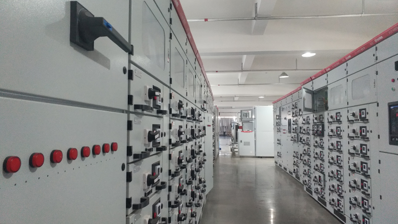
A cement plant MCC room shows the problem. The transformer is large. The room was built for a smaller lineup, and the gas has one route out: the door. Ask for the relief drawing before you order. Start with the motor control center panel layout, then look up.
The accessible face decides the room you build
Arc resistance is claimed per face. A lineup tested on the front only says nothing about the back, and the back is often where cable arrives.
Front-only access means the lineup stands against a wall. That saves floor area and makes maintenance harder, because every drawer leaves through the same face.
Check which faces were closed during the test, then check which faces a technician reaches on a normal Tuesday. Those two lists have to match before the drawing is frozen.
Cable entry needs its own line. Bottom entry keeps the top clear for relief. Top entry competes with the duct for that space. The clash usually appears after the steel is cut.
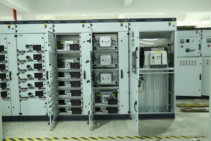
Behind that face sit rows of devices, each with a rating that sets how much energy a fault can release. One motor control bucket is the usual origin, not the incomer at the end of the row.
 Contactor rows
Device rows behind one door.
Every row is a possible origin.
Your fault level picks the report you need
Start from the transformer, not from a catalogue. Its kVA and impedance give the prospective fault current at your terminals, and that figure decides which report is relevant.
A 1000 kVA transformer at 400 V with six percent impedance delivers roughly 24 kA at its secondary terminals. Cable and busbar reduce it, so the figure at the MCC is lower. Get the calculation in writing rather than accepting a guess.
Then match the duration. If the incomer clears a fault in 0.1 seconds, a one-second claim is over-specified. You pay for reinforcement you will never use.
A low voltage motor control center close to the transformer is the hard case. Short cable, high fault level, and no help from upstream impedance.
Before the design starts, read an mcc definition electrical page and see whether it opens with the transformer. If it opens with a lineup drawing, it is a catalogue.
The voltage boundary is worth stating plainly. A medium voltage motor control center supplier quotes against a different test and duration. The faces differ too. Read the report for the voltage you are buying.

Inside the assembly, barriers decide how far the fault travels
Questions that separate a report from an adjective
Six questions do most of the work. Put them in writing and compare the answers side by side. The wording is where a claim starts to drift.
- What current and duration does the report name?
- Which faces were closed, and which stayed accessible?
- How many sections stood in the test cell?
- Where was the gas allowed to leave?
- Which covers and filters were fitted for the test?
- Who signed the report, and on what date?
Most control panel suppliers will send a certificate when asked. Fewer will send the report page. The certificate says a scheme exists, and the report says what was measured.
A control panel builder who has never paid for a test answers with a standard number and a warranty. That is not a measured result, and it should not enter a technical comparison.
Ask two motor control center suppliers these six questions and the gap appears at once. One sends a pdf. The other sends a sentence.
Control panel manufacturers who test on a schedule recognise these questions and answer them in a day. The ones who hesitate are telling you something useful.
Put the fault level on the first page
One page is enough when it carries the numbers. Put the fault level, the duration you need, the faces you will use and the relief route at the top.
Add the room. Ceiling height, wall positions, duct route and the space left for a technician. The relief path follows from those four facts, not from the assembly.
Request the label with the drawings. A tested assembly carries a marking that names the classification and the standard behind it. If the drawing set has no place for that label, the claim will not survive an audit.
Electrical control panel suppliers rarely test what they build. Most buy a tested design and build to it. Fine, provided the certificate names the design they build.
A quality system certified to ISO 9001 proves a process exists. Read the scope line and see whether internal arc testing sits inside it.
Energy matters as well, because a fault is not the only cost. The IEA puts motor-driven systems near half of global electricity use. A lineup specified for the fault level should also be specified for the load it will actually carry.
Frequently asked questions
What does arc resistant actually mean on a motor control center?
Is a type test report enough proof on its own?
Does the room need to change when I buy arc-resistant equipment?
How long does the assembly have to hold?
What is the difference between the low voltage and medium voltage claim?
Can the relief duct be added after the lineup is installed?
What should I keep after handover?
Final thoughts
Arc resistance is a promise with conditions attached. The conditions live in a report, a drawing and a room, and all three have to agree. Buy the report that matches your fault level and your faces, then build the room around it.
Send the transformer rating and the room dimensions
We will tell you which claim your fault level needs, and where the relief route has to go. Then we will list what the report must name.
Contact Giantele