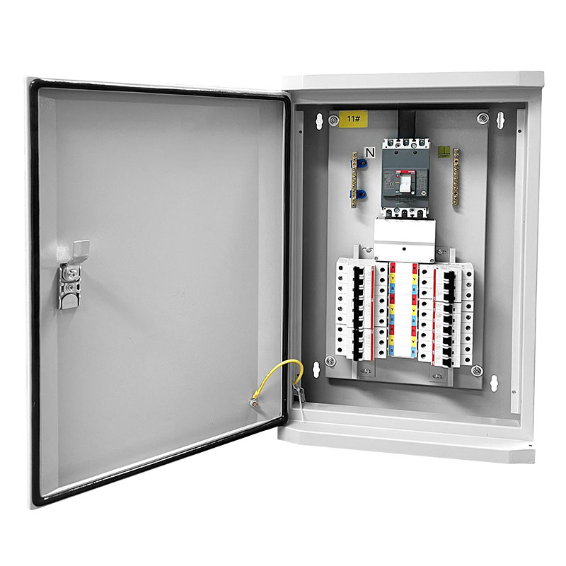
An automation plant is not a normal electrical consumer. A conventional factory tolerates a sag that drops a contactor. Your PLC network, servo drives, and process servers do not. The power distribution system that feeds them must hold voltage, filter harmonics, and switch without glitches that scramble machine logic.
This guide covers what to demand from a power distribution board in an automation environment: voltage architecture, design choices, and the rules of data center power distribution systems. It ends with the maintenance discipline that keeps the whole plant predictable.
Key Takeaways
- Power quality beats raw capacity: Automation loads care about harmonics, voltage sags, and control supply reliability more than nameplate amps.
- Voltage architecture comes first: 400V for drives and motors, 690V for high-power plants, 24V DC control with UPS backup for the automation brain.
- Design for containment: Selectivity and Form 4 isolation stop one feeder fault from taking down the PLC network or a server rack.
- Data centers demand dual paths: Independent A/B feeds, per-circuit monitoring, and maintenance without shutdown are the baseline.
- Maintenance is designed in: A board you cannot service live fails the automation plant, not the other way around.
Why Industrial Automation Changes Your Power Distribution Requirements
Automation shifts the failure mode. A lighting circuit fails and the room goes dark. A distribution feeder serving a drive fails and the entire production cell stops mid-cycle, corrupting work in progress and resetting the batch.
Three load classes dominate an automated plant: variable frequency drives and servos, PLC and sensor networks, and process computers. Each stresses the electric power distribution in a different way.
Drive loads create harmonics; electronics cannot tolerate them
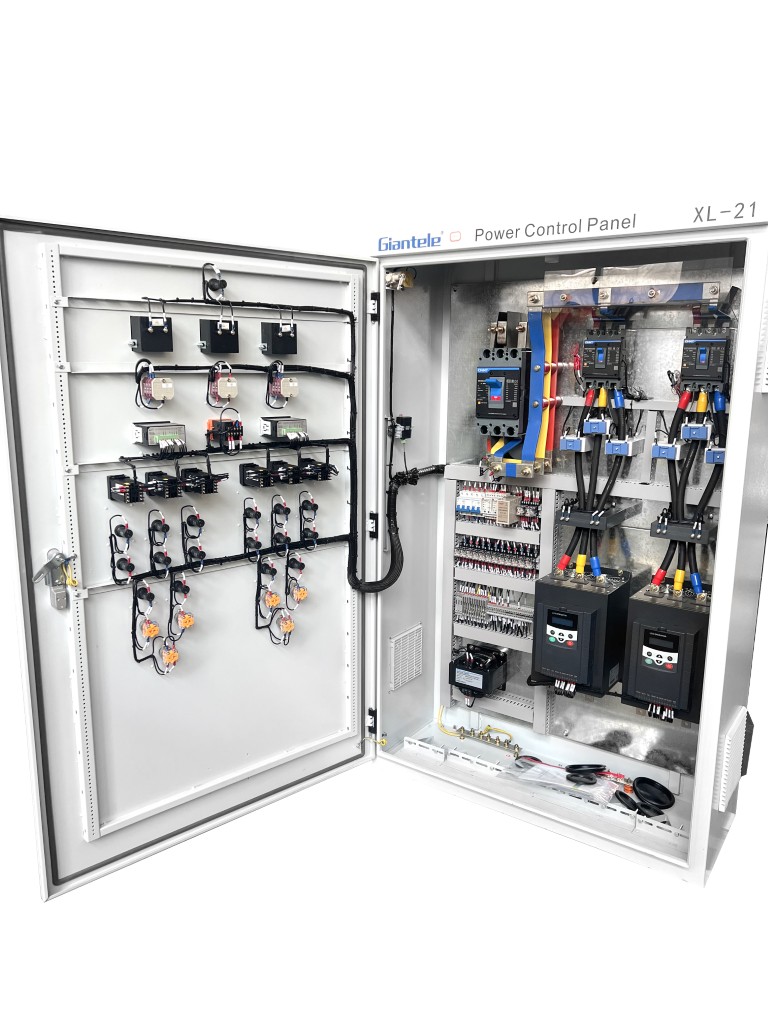
Every VFD and servo drive draws non-sinusoidal current. The distortion feeds back onto the busbars and travels to every other load on the board. PLC power supplies and sensors sit on the same distribution network.
- Harmonic-rated busbar: neutral sized for triplen content, not balanced-load assumptions
- Filtering at the source: drive-side line reactors or active filters before the board
- Dedicated 24V section: control supply isolated from motor transients
Voltage sags are the second threat. Most drives ride through a 100ms dip. PLC processors and industrial computers do not always.
When a large motor starts elsewhere on the same distribution board, the local sag can reset a controller with no ride-through. The power distribution design must separate sensitive and heavy loads onto different sections.
Power Distribution Voltages That Keep Automation Running
Voltage selection is the first decision in power distribution system design. It defines busbar ratings, breaker sizes, and how much of the plant shares one fault domain. The table below maps common voltage architectures to their automation use.
| Voltage | Typical automation application | Why it is used | Watch out for |
|---|---|---|---|
| 400V / 415V AC | Most drives, motors, and panel feeders below 200kW | Widest component availability; standard IEC drive ratings | Voltage sag coordination with neighboring feeders |
| 690V AC | High-power drives, mining, pumps above 200kW | Halves current for the same power; smaller cables and busbars | Drive availability and insulation coordination |
| 24V DC control | PLC racks, sensors, HMI, safety relays | Clean, regulated supply isolated from motor transients | Must come from a dedicated section with UPS or battery backup |
| 48V / 380V DC | Data center and telecom rectifier loads | Direct battery coupling; no conversion losses | DC arc behavior differs from AC; trained maintenance only |
The common mistake is tying the 24V control supply to the same board section as the drives. Every motor start then produces a control supply dip. A dedicated control section, fed through its own transformer or UPS, decouples the automation brain from the power muscles.
For plants that mix automation and heavy process loads, an automatic transfer switch between grid and generator keeps critical board sections alive during a supply loss, which is often the difference between a controlled stop and a crashed batch.
Electrical Power Distribution System Design for Automation
Once voltages are fixed, the electrical power distribution system design decides how faults, heat, and maintenance behave. Five choices dominate an automation installation.
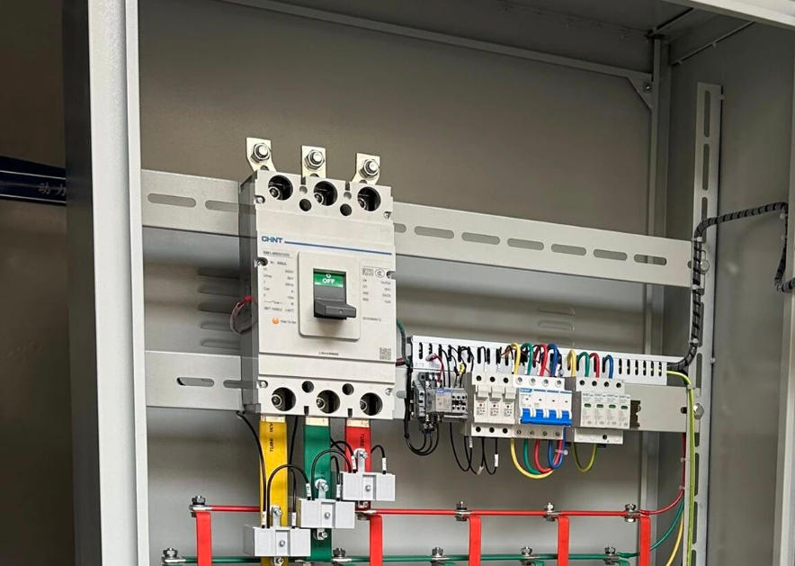
What separates an automation-grade board from a plain one
Power distribution design also means planning for growth. An automated line expands by adding stations, not by adding whole new boards. Leave spare ways, spare busbar capacity, and a free slot for a second incoming when the plant doubles.
The board itself must be verifiable. A IEC 61439 low voltage switchgear assembly carries type tests for temperature rise, short-circuit withstand, and dielectric strength, defined in the IEC standard series.
Those tests separate a board that performs on paper from one that survives the fault it was rated for. Verify the assembly rating before you order, and confirm routine tests ran on your unit before shipment.
Data Center Power Distribution Systems
Data center power distribution systems are the strictest version of automation distribution. A process plant can ride through a short hiccup; a server hall cannot. The board sits between the UPS plant and the racks, and it must never be the single point of failure.
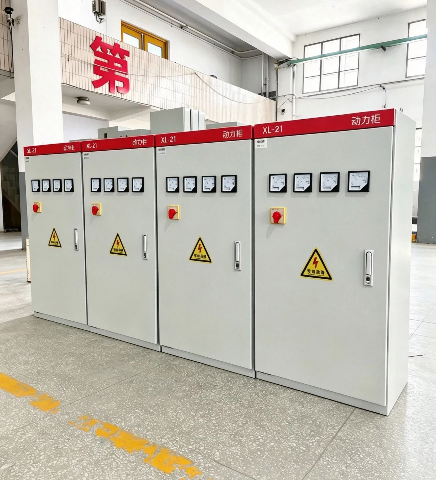
Dual paths, per-circuit metering, live maintenance
Every critical feeder needs two independent paths: A-side and B-side, each with its own board section and its own UPS source. A failure on one side never touches the other.
- Per-circuit metering feeds the facility management system with current, harmonics, and breaker status
- Form 4b separation allows one rack group to be re-fed while adjacent groups run at full load
- Coordination with UPS and gensets keeps the redundant chain intact end to end
Harmonic management matters here too. Modern switch-mode server power supplies generate harmonics that the UPS and standby generators both dislike.
If your facility runs gensets, the harmonic load can overheat generator windings sized for balanced sinusoidal current. An active harmonic filter panel at the board incoming keeps the genset side clean. IRENA data center analyses highlight the same power quality constraints as digital loads scale.
For facilities that also run large motor loads on the same distribution network, an SVG static var generator panel handles the reactive swings that capacitor banks cannot follow fast enough.
Power Distribution Lines and Utility Coordination
The board is the boundary where power distribution lines from the utility meet the plant's own distribution network. Coordination at this boundary decides how an upstream grid event affects the automation plant.
Ask the utility for three numbers before specifying: the available fault level at the incoming, the voltage tolerance of the local grid, and the typical sag frequency.
The first sizes the incoming breaker and busbar withstand. The second tells you whether the plant needs voltage conditioning. The third sets ride-through requirements for the PLC network.
In many African and Southeast Asian industrial zones, grid voltage drifts outside nominal by more than 10% during peak hours.
World Bank power sector assessments show voltage quality, not generation shortfall, drives most equipment failures in automated plants. Automation electronics rated for a tight tolerance window will trip, even though motor loads keep running.
A distribution board with an on-load tap changer or a dedicated conditioned section solves this at the source instead of at every device.
Maintenance and Design for Utilities and Power Distribution Systems
Maintenance and design for utilities and power distribution systems are one conversation, not two. A board designed without maintenance in mind gets ignored until it fails. A board designed for live service gets maintained, and the maintenance records prove it.
Three practices that keep an automation board reliable
Documentation matters as much as the hardware. As-built single-line diagrams, protective device settings, and the selectivity study must live with the board. When a new automation cell is added, the engineer updates the diagram, not just the wiring. An undocumented board is a maintenance liability from day one.
When the existing board cannot be expanded or serviced safely anymore, a new power distribution board designed against your current load list is cheaper than years of band-aid fixes.
Choose a manufacturer that runs factory acceptance tests you can witness, and documents every setting on the unit you receive. To see what a factory acceptance test should cover, how to test a distribution board walks through the routine tests, FAT, and site acceptance steps in order.
Frequently Asked Questions
What makes a distribution board suitable for industrial automation?
Which voltage should I use for my automation distribution board?
How do harmonics affect a power distribution board?
What is Form 4 separation and why does automation need it?
How should a data center distribution board differ from a factory board?
What should I ask the utility before designing the board?
Why is maintenance part of the design conversation?
Final Thoughts
A distribution board for an automation plant is not a commodity box. It is the voltage platform, the fault boundary, and the data source for everything above it.
Spec it against harmonic content, sag tolerance, and live-service maintenance, and the plant runs predictably for twenty years. Spec it like a lighting panel, and the first drive retrofit will expose it.
Send Giantele your single-line diagram and load list for a technical proposal with voltage architecture, Form separation, and monitoring design.
Get a Custom Distribution Board Proposal
Send us your single-line diagram and load list. Our engineers return a verified panel design with voltage architecture and monitoring within 48 hours.