

An electrical transfer switch for generator duty moves a load from one source to another. It does not decide which load deserves to move, and that is the question buyers actually ask. Load management sits above the switch, and it looks different on one set and on several.
Key Takeaways
- Load management is a shedding order. With one generator, the panel drops non essential ways so the set can carry the rest.
- The load schedule is the real specification. Tiers, timings and the largest motor start decide the design.
- A switch box is not an assembly. A generator switch box is a device. An industrial ATS is a built and tested panel.
- Shedding and sharing are different jobs. One generator sheds load. Two generators share it across a bus.
- Integration shows up in documents. A load schedule, a control philosophy and a factory transfer test prove the layer exists.
What load management means when one generator carries the site
With a single set, load management is an order of events. The generator picks up the essential load first. Everything the set cannot carry has to be gone before it closes.
A standby set accepts load in roughly 5 to 15 seconds. If non essential ways are still connected at that moment, the engine stalls on pickup or the voltage collapses. So the panel drops those ways during the transfer.
A generator panel with no shedding logic has to be sized for the whole connected load. Add the shedding order and the same site can run on a smaller set. On most industrial sites the non essential share sits between 20 and 35 percent.
The motor load behind an electrical mcc is usually the biggest single block on that list. Motors also start in steps, so they set the pickup timing for everything else.
Standby capacity keeps growing across Africa and South Asia, and the IEA tracks that shift in its annual outlook work. More standby plant means more panels asked to decide what runs.
The transfer device, the switch box and the panel built around them
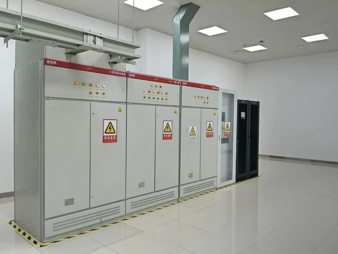
Buyers use three names for three different things. A generator switch box is a small enclosure holding a changeover device for one circuit. A generator switching panel adds protection and an outgoing way. An industrial ATS is an assembly with a busbar, a controller and a load schedule.
Those three scopes appear in the same tender as if they were one product. Ask for the single line diagram of the ats panel before you accept a scope. It shows whether the load side is one way or several.

An assembly is more than a switch box
A switch box is one device in one enclosure. An assembly is a row of sections with a busbar and a load schedule.
That is the gap between a generator switch box and an industrial ats on the same tender line.
Essential, non essential and emergency ways in one panel
A load managed panel splits its outgoing ways into tiers. Each tier carries a different shedding rule, and that rule is fixed at design stage rather than on site.
The electrical panel transfer switch at the head of the panel changes the source. The controller behind it then decides which ways come back and in what order. On a backup generator panel both functions sit in one enclosure and share that controller.
| Load tier | Typical circuits | Shedding rule | What the panel needs |
|---|---|---|---|
| Emergency | Life safety lighting, alarms, pumps for fire duty | Never shed | A dedicated outgoing way, held outside the shedding logic |
| Essential | Process controls, cold rooms, server and control rooms | Shed last, and only on a second start attempt | A labelled way on the essential bus, with its own protection |
| Non essential | Air conditioning, workshops, decorative and office loads | Shed within seconds of the transfer | A contactor the controller can drive, plus a status signal |

Every tier needs its own way, not its own label
A tier that exists only on a drawing cannot be shed during a real transfer.
Each tier needs a separate outgoing device. The non essential tier also needs a contactor the controller can drive.
When two generators share a bus, management becomes load sharing
Two sets change the problem. Instead of choosing what to cut, the controller decides how many sets run and how hard each one works.
Paralleling switchgear sits between the sets and the bus. It synchronises each machine before it closes, then holds a share of the load on each one.
Paralleling gear does the same job on smaller installations with fewer instruments and a simpler controller. The principle is identical, and so is the risk.
A bus fed by two sets is not one bigger set. One machine can fail and the other carries the essential load. That only works if the sharing logic was set up for it.

Four things a paralleling scheme has to answer
Plan the incoming sections for the sets you expect, not only the ones you own today. A board built as modular switchgear can take a third incomer later, and a sealed enclosure cannot.
How to check that the layer is genuinely built in
Integration is a document trail rather than a feature list. A generator transfer panel that manages load arrives with four things at handover. A panel with a controller clipped on top arrives with one.
Ask for the load schedule first. It lists every outgoing way, its tier and its shedding order. Without it, nobody can set the controller correctly on site.
- The load schedule. Every outgoing way, its tier and its shedding order, agreed before the panel is built.
- The control philosophy. One page on what the controller does at a loss of mains, and what it does on return.
- The input and output list. Which output drives which contactor, and what the panel does if that output is lost.
- The factory transfer test. A simulated loss of mains, recorded, with the shedding order timed against the generator pickup.
Work with a supplier running an ISO 9001 system and those records are ordinary production paperwork. Ask for them in the enquiry rather than at the end of the project.
Settle the vocabulary before you compare the documents. A buyer weighing switchgear vs switchboard is really asking which assembly carries the generator incomer.
Matching the load schedule to the generator rating
An electrical transfer switch for generator duty does not change how much load the set sees. The layer above it does, and that is where the rating is decided. You size it to the load that has to survive a transfer.
Take a plant with 800 kVA of connected load and 520 kVA that must stay live. A 600 kVA set carries that load comfortably, as long as the shedding order is reliable. The saving sits in the generator rather than in the panel.
Three numbers decide whether that saving is real. The step load the set accepts, the starting current of the largest motor, and the time the shedding takes.
A mains power distribution board feeding the same plant has to be checked against those numbers too. The generator and the board are sized as one chain, not two.
A panel built to IEC 61439 carries a routine test record for the assembly. The load schedule is what turns that assembly into a managed one. Together they are the two documents that make the layer auditable.
Frequently asked questions
What does integrated load management actually mean on an ATS panel?
Is a generator switch box enough for a small site?
How many load tiers should a panel have?
Can I add a second generator later?
Who sets the shedding order?
Does load management let me buy a smaller generator?
What is the difference between paralleling switchgear and an automatic transfer switch?
What should the factory test prove?
Final thoughts
Load management is the difference between a panel that transfers and a panel that decides. One set needs a shedding order. Two sets need a sharing logic on top of it.
Send your load schedule and your generator rating. Giantele engineers will return a marked panel layout and a technical proposal for the assembly.
Building a standby supply that has to choose what runs?
Send the load schedule, the generator rating and the site conditions. Giantele engineers return a marked layout and a technical proposal. It covers the transfer device, the load tiers and the handover evidence.


