bj4
Home News Products News Motor Control Panel Integration Services for Renewable Energy Systems
Technical Guide · Low Voltage Switchgear

A complete breakdown of the 3-position racking logic, IEC 61439 compliance, true Total Cost of Ownership, and the supplier checklist that African EPCs and plant engineers actually use before signing a PO.

mcc motor control center

Renewable energy sounds simple on paper. Solar panels generate DC, inverters convert it to AC, and motors run. In practice, the gap between a solar array and a working pump station is filled by a motor control panel that nobody specified until commissioning week. You end up with voltage excursions, nuisance trips, and a control system that fights the inverter instead of cooperating with it.

Motor control panel integration services close this gap before it opens. They put the panel designer, the renewable energy contractor, and the end user in the same specification discussion from day one. The result is a panel that starts motors smoothly on inverter power, switches between solar and grid without dropping loads, and protects equipment that cost six figures to install.

Key takeaways

  • Renewable integration is a panel design problem: Solar inverters and wind turbines deliver power differently than grid transformers. Your motor control panel must handle voltage swings, frequency variations, and source switching that grid-only panels ignore.
  • Automation control panel logic makes or breaks renewable projects: The PLC program that decides when to run pumps on solar, when to switch to grid, and when to shed loads determines whether your renewable system runs reliably or trips constantly.
  • Pump control panel applications dominate renewable water projects: Solar-powered borehole pumps in Kenya, wind-driven irrigation in Morocco, and hybrid-grid lift station control panels in Indonesia all need panels designed for variable input power.
  • ATS integration is mandatory for hybrid systems: A control panel without automatic transfer between renewable and grid sources leaves your pumps dead every time clouds cover the solar array.
  • CE certified, IEC 61439 compliant: Giantele renewable energy motor control panels carry CE certification and are designed for solar, wind, and hybrid applications across Africa, the Middle East, and Southeast Asia.

Why renewable energy needs different motor control panel design

A grid-fed motor control panel assumes stable voltage and frequency. A 400V motor expects 400V plus or minus ten percent. A 50Hz contactor coil expects 50Hz. Grids deliver this by design. Solar inverters and wind turbines do not.

An off-grid solar system with battery storage varies its output voltage by 10-15% as battery state of charge fluctuates. A wind turbine changes frequency with gust speed before the inverter catches up. An industrial control panel designed for grid power trips its undervoltage relay every time a cloud passes. One designed for renewable integration widens its protection tolerance, adds time delays to ride through transient dips, and coordinates with the inverter's own protection curve.

Integration Design

Grid vs renewable: what your panel must handle differently

  • Voltage tolerance: Grid panels expect stable 400V plus/minus 10%. Renewable panels accept 340-460V without tripping, with programmable time delays on undervoltage.
  • Frequency ride-through: Wind turbine output frequency swings during gusts. Panel protection relays need wider frequency windows or response delays measured in seconds, not cycles.
  • Source synchronization: When an ATS switches between solar and grid, the panel must coordinate the transfer so motors do not experience out-of-phase reconnection that damages windings.
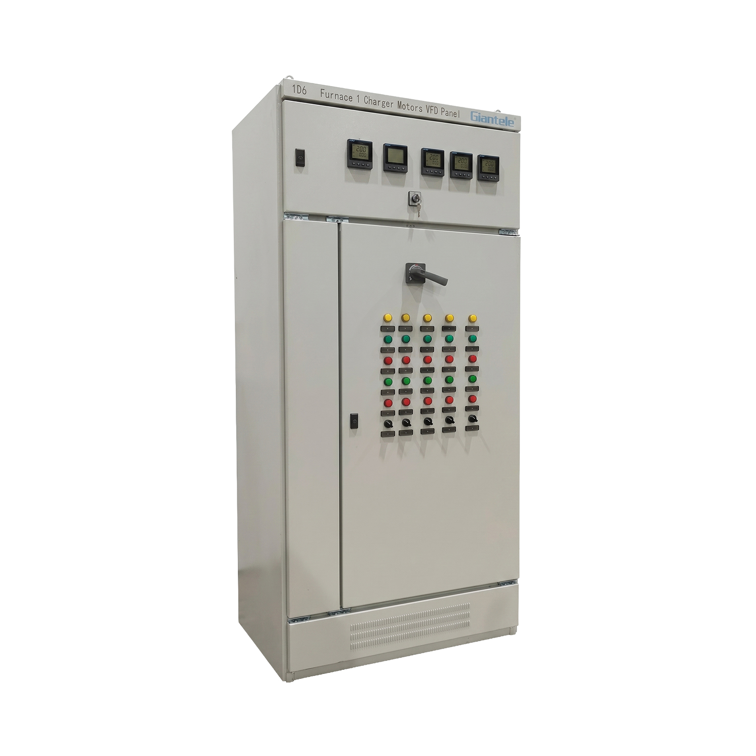
MCC Panel motor control center panel for renewable energy integration with industrial enclosure
i
Technical Note Solar inverters from major manufacturers are tested per IEC 62109 for safety and IEC 61727 for utility interface. But these standards cover the inverter, not the motor control panel downstream. Your panel designer must bridge the gap between inverter output characteristics and motor protection requirements. This is the integration layer that most projects discover they need during commissioning.

Automation control panel design for renewable energy integration

An automation control panel for renewable energy does more than start and stop motors. It manages the energy source. When solar irradiance drops, it decides which pumps keep running and which shed load. When battery voltage falls below a threshold, it commands the generator start or switches to grid. These decisions live in the PLC program, not in the contactor wiring.
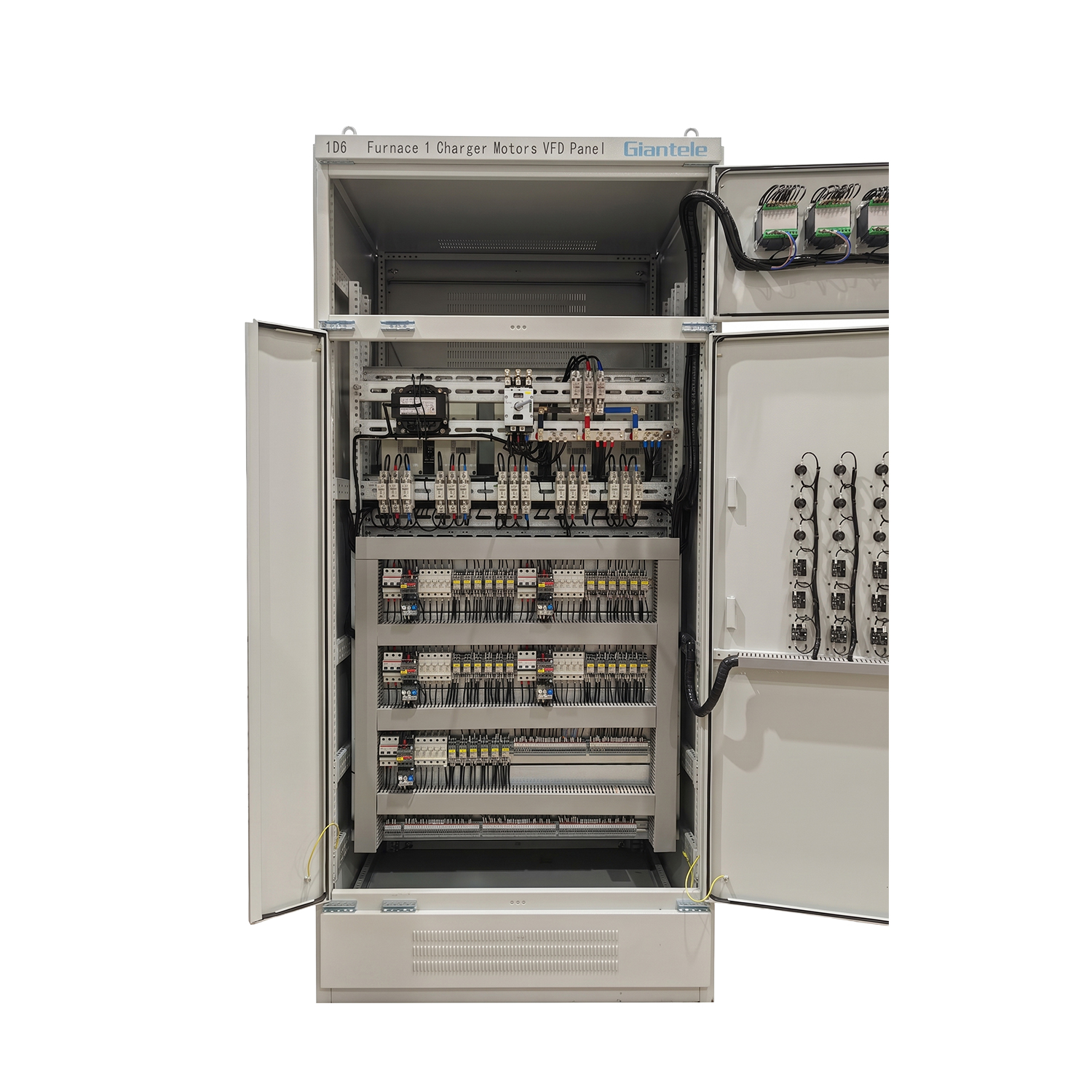
automation control panel internal layout with PLC wiring for renewable energy systems
PLC Design

PLC control panel design for renewable energy: four tasks your program must handle

1
Source selection logicMonitor solar inverter output, battery state of charge, and grid availability. Switch between sources based on priority, not just availability. Solar-first with grid backup is standard. The program needs hysteresis to prevent oscillation between sources.
2
Load shedding sequenceWhen renewable power drops, shed non-critical loads first. Irrigation pumps stop before drinking water pumps. The PLC needs a priority table, not a simple on/off threshold. Getting the sequence wrong means the wrong equipment stops first.
3
Soft start coordinationStarting a 30kW pump on inverter power draws 2-3 times running current momentarily. The PLC must stagger motor starts so the inverter never sees simultaneous inrush from multiple motors. Overlapping starts trip the inverter on overload.
4
Remote monitoring integrationRenewable sites are often unattended. The PLC uploads pump status, energy source, and alarm data via Modbus or Ethernet to a SCADA system or cloud dashboard. Operators in Nairobi monitor a borehole in Turkana without driving six hours.

Automated control systems for renewable energy must handle the edge cases. What happens when battery voltage is at 48.2V and the cutoff is 48.0V? The PLC enters a hysteresis band and holds the last state. What happens when the grid returns after a four-hour outage? The panel waits 180 seconds for voltage stabilization before reconnecting motors, preventing the inrush current that trips the main breaker. These details are not in the inverter manual. They are in the panel designer's integration specification.

Pump control panel applications in renewable water systems

Solar-powered water pumping is the fastest-growing renewable application in Africa and Southeast Asia. A pump control panel for a solar borehole in northern Kenya runs differently than one for a wind-powered irrigation system in coastal Morocco. The panel design changes with the energy source.

Pump control panel: renewable energy source comparison
Energy sourcePanel requirementTypical pump typeKey control challengeSolution
Solar PV onlyDC-compatible VFD or DC pump controllerSubmersible boreholePower drops to zero at nightDaytime storage tank, no battery needed
Solar + batteryAC soft starter with wide voltage toleranceSurface centrifugalBattery discharge depth managementPLC-controlled load shedding at 40% SOC
Wind turbineFrequency-tolerant overload relayIrrigation boosterFrequency swings during gustsDelayed trip on frequency deviation
Hybrid solar-gridATS-integrated duplex pump panelCommunity water supplySource switching without water hammerSoft stop/start during transfer

A sump pump control panel on a solar-powered drainage system faces its own challenge. The pump runs intermittently based on float switch level. On grid power, it starts whenever the float triggers. On solar, it should run during peak sun hours if possible. The PLC delays non-critical sump pumping to midday when solar output peaks. This saves battery cycles for critical loads at night. Simple logic, big impact on battery life and system reliability.
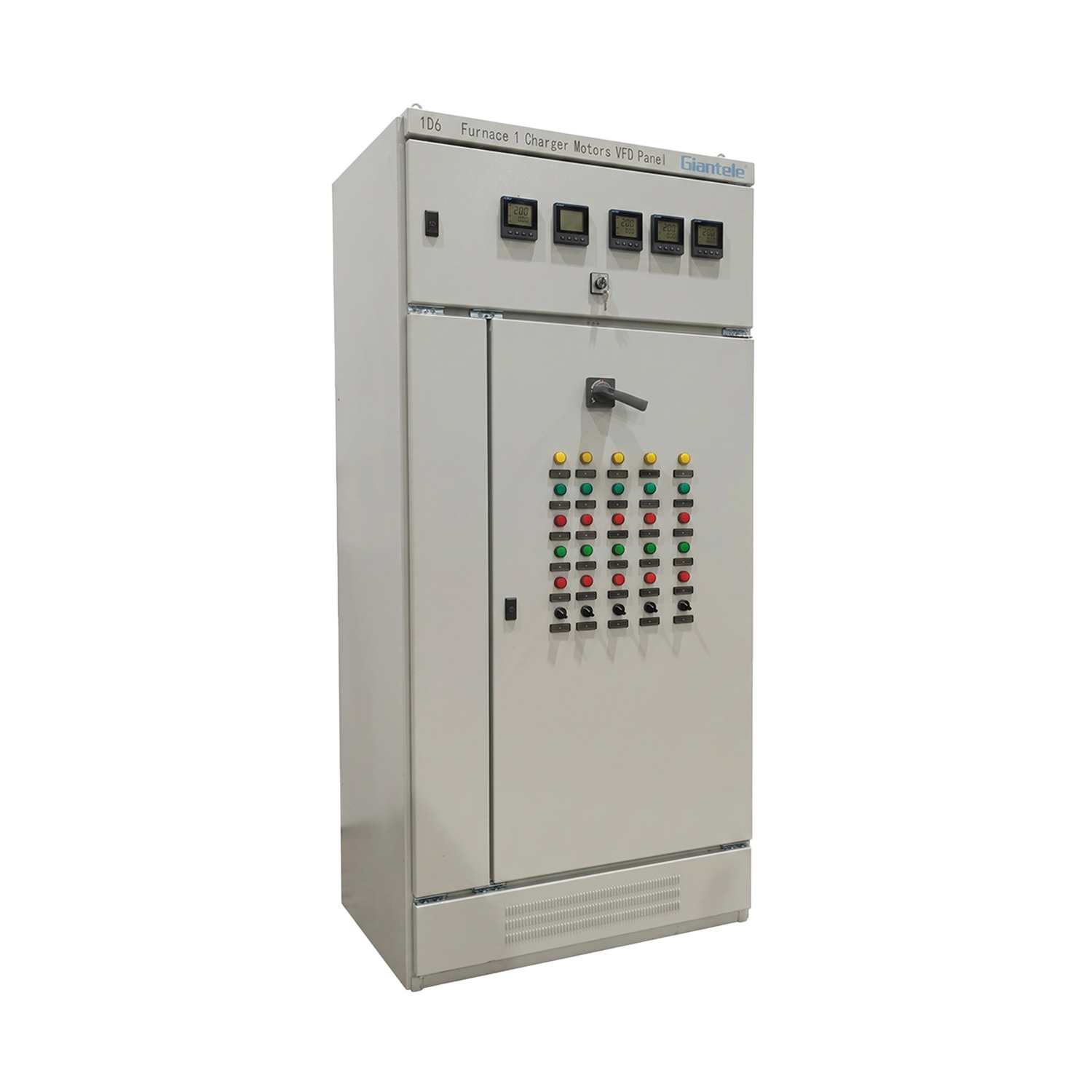
VFD Panel VFD control panel for solar pump applications in renewable energy systems
Pump Control

Duplex pump and lift station control for renewable projects

A duplex pump control panel on a hybrid solar-grid system runs the duty pump on solar during the day and the standby pump on grid at night. Automatic alternation evens out the wear. The panel's PLC tracks running hours per energy source and rotates pumps accordingly.

A lift station control panel in an off-grid solar community in Uganda needs different logic than one on municipal power. The solar lift station fills a holding tank during daylight. At night, it runs only on high-level alarm, using battery reserve. The panel's priority logic makes this decision autonomously.

Without this integration, the lift station either drains the battery bank overnight or stops pumping entirely after sunset. Both outcomes are unacceptable for a community of 5,000 people.

!
Pump Sizing Warning The most common failure in solar pump projects is matching the pump motor to peak solar output rather than average daily output. A 15kW pump sized for noon sun output stalls at 10 AM and 3 PM. Size the pump for the minimum reliable solar window and add storage, not the other way around. The motor control panel cannot fix a pump that is 50% oversized for its energy source.

Control panel layout design for hybrid renewable-grid installations

Control panel layout design for hybrid systems must physically separate grid-connected and renewable-source components. A single enclosure with interleaved grid and solar feeders creates a safety hazard during maintenance. The technician isolates the grid breaker but the solar inverter continues feeding the DC bus.
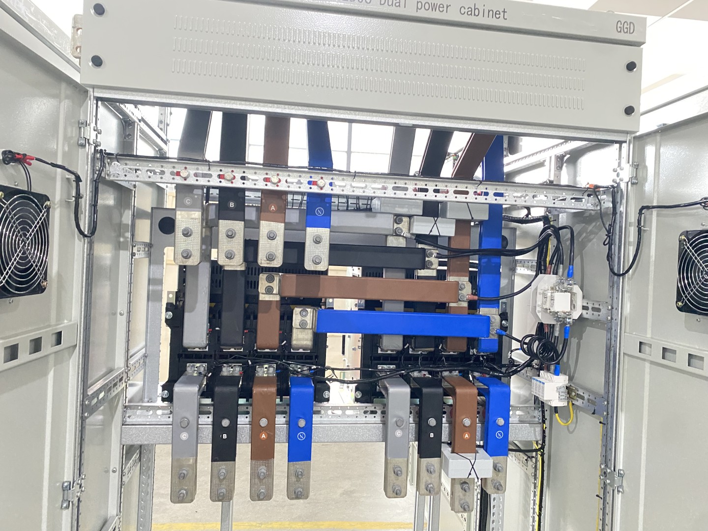
busbar layout design for motor control panel in renewable energy integration applications
Layout Principles

Panel layout: three physical rules for hybrid renewable systems

1
Separate source compartmentsGrid incomer, solar inverter feed, and generator input each occupy a dedicated busbar section with visible isolation. A technician must see exactly which source is live before opening any door.
2
DC segregationIf the panel includes DC circuits from solar charge controllers, these must be physically separated from AC compartments by a grounded metal barrier. DC arcs are harder to extinguish than AC arcs and need dedicated arc chute protection.
3
Thermal management for inverter heatA 100kW solar inverter inside or adjacent to a motor control panel enclosure adds 2-3kW of continuous heat. Ventilation must be sized for this load plus the contactor and busbar heat. Undersized cooling cooks components within two years in tropical installations.

Electrical control panel design for renewable integration must also handle the grounding scheme. Solar arrays are typically ungrounded or resistance-grounded on the DC side. Grid transformers are solidly grounded on the AC side. The panel's grounding bus must accommodate both without creating ground loops that trip residual current devices. This is not a detail. It is the reason many renewable projects fail their first ground-fault test.

Manufacturing control systems for renewable energy equipment

Manufacturing control systems for renewable energy production lines need their own motor control integration. A factory producing solar mounting structures in Kenya runs roll-forming machines, punch presses, and galvanizing lines. These are motor-driven loads that benefit from renewable power integration.

1
Load auditCatalog every motor load, its kW rating, duty cycle, and criticality. Separate essential loads from deferrable loads for the load shedding program.
2
Source integration designDesign the ATS and busbar configuration. Define source priority: solar first, grid second, generator third. Specify the generator ATS transfer time and synchronization requirements.
3
Panel fabrication with FATAssemble and test the panel. Verify source switching under load, load shedding sequence, and communication with the inverter and battery management system. Document every test result.
4
Commissioning with renewable contractorCommission the panel together with the solar installer or wind turbine technician. Test every operating mode: solar-only, grid-only, hybrid, and backup generator. Train operators on source management.

A VFD control panel in a manufacturing plant powered by solar reduces energy consumption by matching motor speed to process demand. A 50Hz fixed-speed fan running at 40Hz through a VFD draws roughly half the power. On a solar-powered system, that 50% reduction means the same PV array powers two production lines instead of one. The VFD investment pays back in reduced solar array size, not just in electricity savings.

Automatic power factor correction matters even more on renewable systems. Solar inverters produce active power (kW) but not reactive power (kVAR). Motors still need reactive power. If the grid provides it, you pay for kVAR demand. An Static Var Generator panel supplies reactive power locally, eliminating kVAR charges and reducing the inverter's apparent power burden. According to IRENA, power factor correction in solar-hybrid industrial systems typically recovers 8-15% of inverter capacity that would otherwise be wasted on reactive power delivery.

Integration Tip Always specify one integration test that runs the complete sequence: solar to grid transfer under full motor load. Most commissioning failures happen during source transfer, not during steady-state operation. If the panel transfers cleanly at full load once, it will transfer cleanly a thousand times. Test what breaks, not what works.

Frequently asked questions

What motor control panel integration services do renewable energy projects need?
Renewable projects need panel design that accounts for inverter output characteristics, source switching between solar/grid/generator, load shedding based on available renewable power, and coordination with battery management systems. Standard grid-fed panel designs do not handle these functions. Integration services cover specification, PLC programming for source management, panel layout with source segregation, factory testing with simulated renewable input, and commissioning with the renewable contractor present.
Can an automation control panel manage solar and grid power automatically?
Yes. An automation control panel with a properly programmed PLC monitors solar inverter output, battery state of charge, and grid availability. It switches between sources based on configurable priority and timing. Solar-first with automatic grid fallback is standard. The PLC prevents oscillation between sources with hysteresis bands and minimum run-time timers. Without this automation, operators manually switch between sources and inevitably misjudge battery capacity.
How does a pump control panel work with solar power?
A solar-compatible pump control panel uses either a DC pump controller for direct PV connection or an AC soft starter/VFD with wide voltage tolerance for inverter-fed systems. The panel's protection relays must accept the voltage and frequency variation that solar inverters produce. Pump start coordination prevents multiple pumps from starting simultaneously and overloading the inverter. The PLC may schedule non-critical pumping during peak solar hours to conserve battery capacity.
What PLC control panel design features does a renewable system need?
The PLC program must include source selection logic with hysteresis, prioritized load shedding when renewable power drops, staggered motor start coordination to prevent inverter overload, and communication with the inverter and battery management system over Modbus or Ethernet. Analog inputs for solar irradiance sensor and battery voltage enable predictive load management. Remote monitoring uploads performance data to SCADA for unattended sites.
Can you integrate a duplex pump control panel with a hybrid solar system?
Yes. A duplex pump control panel on a hybrid system runs the duty pump on solar during daylight and automatically switches to grid or battery for the standby pump at night. The PLC tracks running hours per energy source, alternates pumps to even out wear, and never starts both pumps simultaneously on inverter power. When grid power feeds the standby pump, the solar array continues charging batteries for the next daylight cycle.
How does control panel layout design differ for renewable energy?
Hybrid renewable panel layouts physically separate grid, solar, and generator source compartments with visible isolation points. DC circuits from solar charge controllers are segregated from AC sections by grounded metal barriers. Thermal management accounts for inverter heat load inside or adjacent to the enclosure. Grounding bus design prevents ground loops between the ungrounded DC solar array and solidly grounded AC grid side.
Are Giantele renewable energy control panels CE certified?
Yes. All Giantele motor control panels carry CE certification under IEC 61439. Panels for renewable integration undergo additional factory testing with simulated variable input voltage and frequency to verify ride-through performance. Every panel ships with FAT report, as-built drawings, PLC program documentation, and a commissioning checklist covering solar, grid, and generator operating modes.

Final thoughts

Motor control panel integration for renewable energy is not about building a different panel. It is about building a smarter one. The same contactors, the same busbars, the same enclosure. But the protection settings, the PLC program, the ATS coordination, and the factory testing all change because the energy source changed.

Send Giantele your renewable energy project specification: solar array capacity, motor list, and site conditions. Our engineering team returns an integration proposal with panel design, PLC functional description, and budget pricing within 48 hours.

Get a Renewable Energy Panel Integration Proposal

Send your solar or wind project specs plus motor list. We return a verified integration design with panel layout and budget within 48 hours.
Request Proposal
GE

Reviewed by the Giantele Engineering Team

13+ years of motor control panel manufacturing with renewable energy integration experience across solar, wind, and hybrid systems. Products deployed in 50+ countries with CE certification under IEC 61439 and ISO 9001 quality management.

✓ IEC 61439 Verified✓ ISO 9001:2015✓ CE Certified✓ Renewable Ready

Get a Quote in 12 Hours

Send your project specs — our engineers reply with a verified price and IEC-compliant drawing within one working day.

MAKE AN ENQUIRY
or chat directly

+

Years

+

Countries

h

Reply
Build Your Switchgear Project with a Verified Chinese Manufacturer
Whether you are an EPC, a plant engineer, or a regional distributor — we deliver IEC-compliant low & medium voltage switchgear with full documentation, container-ready packing, and African-port logistics support.
12-hour response from our engineering team — not a sales bot.
NDA-friendly — share your single-line diagram without disclosing project name.
OEM/ODM welcome — your brand, our 13-year manufacturing backbone.
Free spec review — we flag IEC compliance gaps before you tender.
Request Engineering Consultation
MAKE AN ENQUIRY

Related Blogs

Related Products

The cylindrical power capacitor delivers reliable reactive power compensation for your electrical system, and it supports power factor correction (PFC) to cut energy waste and lower utility costs; this low voltage power capacitor works well in both industrial and commercial settings, and it outperforms traditional oil-immersed capacitor with a safer, more eco-friendly dry-type capacitor design, while it also follows international standard IEC60831-1:2002 to ensure stable performance, boosts voltage quality, reduces reactive power loss effectively, and suits high-demand power systems.
Inquire
The air insulated switchgear (AIS) redefines eco-friendly power distribution for 12kV three-phase AC systems. This sf6 free switchgear replaces harmful greenhouse gases with zero-grade dry air or 99.99% pure nitrogen, achieving a material recycling rate exceeding 90%. Furthermore, this medium voltage switchgear design combines a compact footprint with strong environmental adaptability for both indoor and outdoor deployment. As a result, this ring main unit delivers maintenance-free, intelligent, and environmentally responsible distribution across a wide range of industrial and urban applications.
Inquire
The Ring Main Unit delivers a new generation of environmentally friendly power distribution for 12kV three-phase AC systems. This advanced solid insulated switchgear uses fully sealed epoxy resin encapsulation, eliminating SF6 gas entirely. As a result, this sf6 free rmu operates safely across extreme temperatures, coastal humidity, and high-altitude plateau environments. Furthermore, its modular architecture supports both indoor and outdoor deployment in a ring type distribution network, and is suitable for various application scenarios.
Inquire
The static var generator (SVG) panel serves as the ultimate solution for high-precision power quality in modern industrial grids. This professional reactive power compensation equipment effectively eliminates voltage flicker while stabilizing the entire electrical distribution network. Furthermore, this Power Factor Correction Device utilizes high-speed IGBT switching to ensure consistent voltage at the receiving end. Consequently, our advanced technology delivers superior reactive power management compared to traditional mechanical switching systems.  
Inquire
We will work with other excellent partners to deliver more high-quality products to the world.
MAKE AN ENQUIRY

Copyright © Zhejiang Zhegui Electric Co., Ltd. is founded in Zhejiang, China.   SItemap