


A power distribution board takes an incoming electrical supply and turns it into organised, protected outgoing circuits for a building, plant, or infrastructure project. Its purpose is not simply to divide power. It gives each feeder a controlled route, provides a way to isolate a fault, and makes operation and maintenance more manageable. For project owners, the board is the point where system safety, continuity, expansion, and visibility meet. This guide explains the practical role of a power distribution board in industrial and commercial installations, with selection questions procurement teams should ask before approving a design.
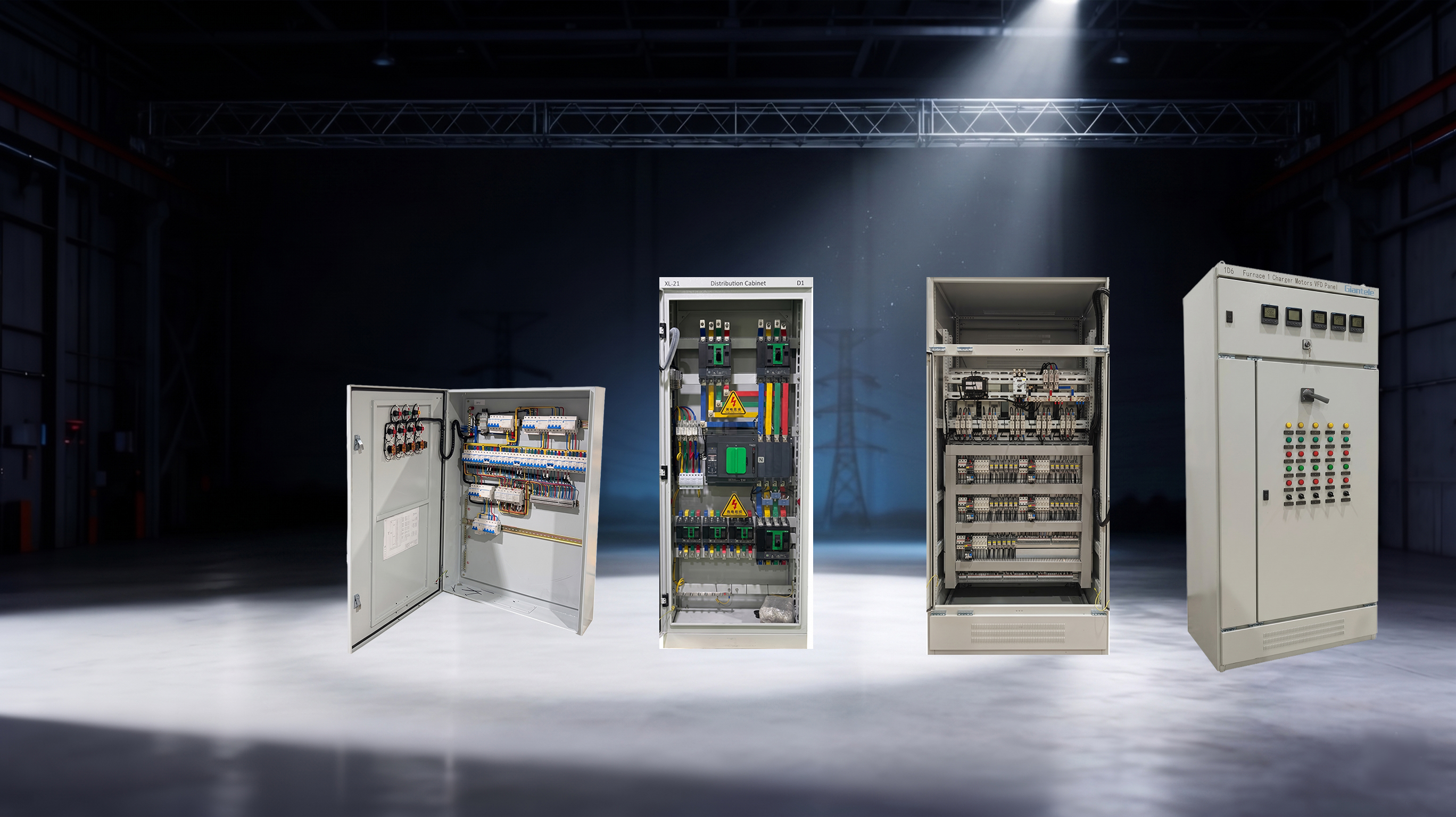
Key Takeaways
A power distribution board divides incoming power into protected circuits and creates an orderly place to control them.
Its protective devices help limit the effect of overloads, short circuits, earth faults, and switching work.
The right arrangement supports selective fault isolation, safer maintenance, load management, metering, and future expansion.
Selection depends on the single-line diagram, prospective fault level, load profile, environment, access method, and local installation rules.
The practical use of a power distribution board
The first use of a power distribution board is to make bulk power usable. A transformer, generator, utility incomer, or transfer arrangement may deliver a substantial supply to a site. Equipment does not all use that supply in the same way. Lighting, socket outlets, HVAC plant, pumps, production machinery, process skids, IT loads, and fire-related services need separate feeders with different protective settings and operating priorities. The board places those outgoing ways in a common assembly so power can be distributed with purpose rather than through a collection of improvised connections.
In a typical low-voltage arrangement, the incomer enters through a main switching and protection device. Busbars then carry the supply across the assembly, and each outgoing feeder is protected by an MCB, MCCB, fuse-switch, or another suitable device. A fault on one branch should be cleared by the device closest to that branch where the protection study permits it. That is the operational value of segmentation: a problem at one motor or lighting circuit does not automatically remove every other load from service.
The terms used in drawings vary. A project may call the assembly an electrical distribution board, distribution panel, panelboard, DB, or switchboard. The name alone is less important than the duty it performs in the system and the verified construction of the assembly. For an upstream installation, a main distribution board normally sends power onward to sub-distribution boards or major plant feeders. A downstream board generally serves a zone, floor, process area, or final circuits.
How the board protects people, equipment, and continuity
Circuit protection is the most obvious function, but it should be considered as a coordinated system rather than a list of breakers. Overcurrent protection helps prevent conductors and equipment from carrying damaging current for too long. Short-circuit protection must interrupt or withstand the fault duty expected at that location. Earth-fault and residual-current protection may be needed where the installation design and local rules call for it. Isolation allows authorised personnel to work on a defined section after appropriate safety procedures have been followed.
A well-planned power distribution board also contributes to continuity. When a branch device trips, operators can identify the affected circuit from the label schedule, isolate it, investigate the load, and restore the unaffected areas. In a manufacturing environment this may protect production on parallel lines. In a commercial building it may keep essential areas supplied while a local defect is corrected. The result is not a guarantee of zero downtime; it is a better ability to confine an incident to the smallest practical part of the installation.
Key functions at a glance
Function | What the board does | Why it matters to the project |
|---|---|---|
Load distribution | Routes the incomer to separate feeders | Lets different zones and equipment receive the supply they require |
Circuit protection | Houses protective devices matched to outgoing circuits | Helps prevent damage during overloads and faults |
Isolation | Provides defined switching points | Supports safer inspection, maintenance, and replacement work |
Fault isolation | Separates a faulty feeder from healthy feeders | Can reduce the operational impact of a local incident |
Metering and monitoring | Provides a location for meters, indicators, or communications | Supports operating decisions and energy management |
Expansion | Provides spare ways or designed capacity where appropriate | Makes later fit-outs less disruptive |
The components that make the function possible
An enclosure is only the visible part of the assembly. Inside, the incomer device manages the incoming source and provides a principal point of disconnection. Busbars distribute current to outgoing devices. The protective devices are selected for current rating, utilization category where relevant, interrupting or breaking capacity, and the coordination required by the design. Neutral and protective-earth arrangements must suit the earthing system and the circuit design. Terminals, cable space, gland provisions, barriers, labels, and mechanical supports matter because an electrically correct schematic can still become difficult or unsafe to install and maintain if the physical arrangement is poor.
For larger schemes, separation between busbar, switching, and cable compartments can make a meaningful difference to access and service continuity. The right form of separation is a project decision, not a decorative specification. It should reflect who needs access, which parts may remain energised, the maintenance plan, and the consequences of an interruption. Metering can be equally important when a site needs to distinguish between tenants, departments, high-energy equipment, or critical loads.
Zhejiang Zhegui Electric Co., Ltd. describes its power distribution board solutions in the context of industrial control and distribution applications. Buyers should still begin with their own system data: the board must be designed around the actual one-line diagram, installation conditions, and protection requirements rather than selected from a nameplate alone.
Load distribution is also a planning tool
The phrase load distribution does not mean dividing every circuit equally. It means arranging feeders so that the electrical system matches the way the facility operates. Three-phase loads need sensible phase balance. Large motors may need dedicated feeders and coordinated starting arrangements. Lighting and general-power circuits often need separate treatment so a fault does not unnecessarily darken an entire working area. Critical and non-critical loads may require separate distribution paths, generator interfaces, or documented load-shedding priorities.
The process starts with a load schedule. Designers identify connected loads, expected demand, diversity assumptions where appropriate, operating modes, starting currents, power quality considerations, and growth plans. They then determine incomer rating, busbar rating, outgoing feeder duties, and spare capacity. A simple planning relationship is: estimated demand = sum of applicable load demands after the project’s approved diversity assumptions. That relationship is a starting point, not a substitute for engineering judgement, manufacturer data, or local code requirements.
Future capacity should be treated carefully. Empty ways are useful only if there is adequate busbar capacity, cable space, fault-duty allowance, and physical access to use them later. Conversely, an oversized board can make a small project unnecessarily expensive and difficult to install. The goal is a documented margin aligned with the owner’s expansion plan.
Choosing the right board for an industrial project
Start selection with the system rather than a catalogue photograph. Confirm the nominal voltage and frequency, earthing arrangement, source characteristics, estimated demand, prospective short-circuit current, incoming and outgoing cable routes, and installation environment. A board for a dry indoor electrical room has different enclosure and access requirements from one exposed to dust, humidity, corrosive conditions, or outdoor weather. If an automatic transfer switch, generator, photovoltaic system, or energy-storage interface is involved, clarify the source operating modes and interlocking needs early.
Protection coordination deserves particular attention. The main protective device must not be selected only because its current rating looks suitable. Its breaking capacity, setting range, time-current characteristics, and relationship with downstream devices affect whether a fault is cleared safely and selectively. Ask the design team for the protection study or the basis of coordination. Also confirm whether the assembly’s verified short-circuit withstand duty covers the actual fault level at its point of installation.
For many commercial and industrial projects, EN IEC 61439 is part of the specification conversation because it addresses low-voltage switchgear and controlgear assemblies. A request for compliance should be followed by practical questions: which part applies, what verification evidence is available, what configuration does it cover, and whether any project-specific modification changes the verified design. Giant Electric’s guidance on selecting a power distribution board highlights the importance of matching current, fault duty, enclosure conditions, and application needs rather than treating compliance wording as a checkbox.
Installation, commissioning, and maintenance
The board’s usefulness depends on installation quality. The location should provide appropriate working access, environmental protection, cable entry, ventilation where required, and clear labelling. Connections must be made to the manufacturer’s torque requirements by qualified personnel. Protective conductor continuity, insulation resistance, functional switching, phase identification, and protection-device settings should be checked as part of the approved commissioning process. Local rules and the project’s safe system of work govern the exact tests and responsibilities.
After energisation, keep the documentation alive. Updated single-line diagrams, circuit schedules, breaker settings, test records, and change logs are operational tools, not just handover paperwork. Periodic inspection can identify loose connections, signs of overheating, moisture ingress, corrosion, damaged labels, repeated nuisance trips, or newly added loads that no longer fit the original design. Thermographic surveys and power-quality investigations may be appropriate where the maintenance strategy and operating conditions warrant them.
Giant Electric can be a useful manufacturing contact when a project needs an assembly aligned with a defined application. The specification, however, should always be signed off by the responsible electrical professionals for the project and jurisdiction.
Conclusion
The use of a power distribution board is to convert a site’s incoming electrical supply into controlled, protected, maintainable circuits. It supports more than power delivery: it gives a project a framework for fault isolation, isolation work, load organisation, monitoring, and future changes. The best choice is not simply the board with the highest nominal rating. It is the assembly whose protection, construction, environment rating, access arrangement, and verification evidence align with the installation it will serve.
FAQs
What is the difference between a distribution board and a switchboard?
Terminology varies by market and project scale. Both terms can describe assemblies that receive power and supply outgoing feeders. The practical distinction should come from the system duty, ratings, construction, and applicable standard—not the label used in a sales description.
Why does every outgoing circuit need protection?
Each circuit has its own conductor size, load behaviour, and fault exposure. A properly selected protective device helps disconnect a fault or overload before it damages the circuit or creates a wider interruption. Device selection must be coordinated with the system design.
Can a power distribution board feed a generator-backed load?
Yes, provided the overall design includes suitable source-transfer, interlocking, protection, earthing, and operating arrangements. A generator connection is a system design issue; it should not be added to a standard board without engineering review.
How many spare ways should a new board have?
There is no universal percentage. The right allowance depends on planned fit-outs, available busbar capacity, space, anticipated loads, and the owner’s expansion forecast. Record the rationale in the project specification.
What documents should be requested at handover?
Typical handover information includes the approved single-line diagram, circuit schedule, assembly drawings, data sheets, verification or test records as applicable, protection settings, installation instructions, and maintenance guidance. The exact package depends on the contract and local requirements.