


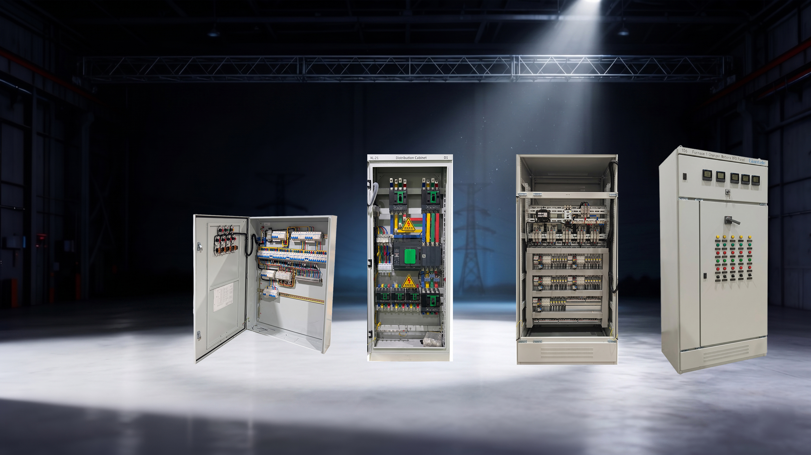
A power distribution board is an electrical assembly that receives an incoming supply and distributes it to multiple protected outgoing circuits. It sits between the source of electrical power and the loads that consume it, giving designers and operators a structured way to switch, protect, isolate, and monitor circuits. In a small premises it may serve lighting and socket circuits. In an industrial site it may feed motors, HVAC equipment, process lines, sub-boards, and critical services. Understanding the board’s role helps buyers evaluate more than dimensions and amperes: it reveals how the assembly supports safety, availability, and controlled growth.
Key Takeaways
A power distribution board is the organised transfer point between an incoming supply and separate outgoing circuits.
It normally combines switching, busbars, protective devices, terminals, and an enclosure designed for the duty.
A board must be chosen using real system information, especially supply characteristics, load schedule, fault level, environment, and operating requirements.
Good circuit identification and verified documentation are essential to its safe long-term use.
A definition that works on a real project
At its simplest, a power distribution board divides one electrical feed into several subsidiary circuits. That concise definition is useful but incomplete. A real board must also make the circuits accessible, protected, identifiable, and suitable for their environment. It can contain one incomer or more than one source arrangement, a busbar system, branch circuit protection, neutral and earth bars, terminals, metering, indicators, and space for wiring. The design can range from a compact final board to a compartmented main assembly supplying several sections of a facility.
The board is often called a distribution panel, electrical DB, panelboard, or circuit breaker panel. These terms overlap, and regional usage differs. Instead of assuming two names describe identical products, compare the duty. Ask where the assembly sits on the one-line diagram, what source it receives, what it feeds, who will operate it, and what fault level exists at that point. Those answers define the product requirement more reliably than a generic category name.
For example, an upstream main distribution board may receive power from a transformer and feed sub-main boards or large mechanical loads. A local distribution panel may receive a feeder from that main board and supply a floor, workshop, tenant area, or equipment group. Both perform distribution, yet their current duty, cable arrangements, protection coordination, and service-continuity needs can be very different.
How electricity moves through the assembly
The incoming supply enters through an incomer. Depending on the arrangement, it may pass through a main isolator, circuit breaker, fuse-switch, changeover device, or another designed interface. Conductors then connect to the busbar system, which carries power to the outgoing devices. Each outgoing feeder has a protective device selected for the cable and load it serves. From there, the feeder cable supplies a downstream board or an end-use load.
The sequence can be described in plain terms: source supply → incomer → busbars → outgoing protective device → feeder cable → load or downstream board. The board makes that sequence repeatable and controlled. If a downstream problem occurs, the appropriate protective device should respond according to the protection scheme. If maintenance is required, the installation’s authorised procedures use the defined isolation points and labels to identify the correct circuit.
What is usually inside?
Element | Function in the power distribution board | Project question to ask |
|---|---|---|
Incomer | Connects and controls the incoming supply | Does its rating and fault duty match the source point? |
Busbars | Carry supply to outgoing circuits | Are material, rating, insulation, and supports suitable for the duty? |
Outgoing devices | Protect and switch individual feeders | Are settings and breaking capacities coordinated with the design? |
Neutral and PE bars | Provide termination points for system conductors | Do they suit the earthing arrangement and circuit requirements? |
Enclosure and partitions | Provide physical protection and access control | Is the construction appropriate for the site environment and maintenance plan? |
Labels and documents | Connect physical circuits to the electrical design | Can operators identify every device and its purpose quickly? |
Why the busbar system matters
The busbar system is not a passive detail. It carries the board’s internal distribution current and must withstand normal operation as well as the stresses defined by the project’s fault conditions. Its rating must be considered alongside ambient temperature, enclosure layout, ventilation, connection arrangement, and any derating factors that apply. The connection of incoming and outgoing conductors must also be physically workable. A nominally adequate busbar does not solve a problem if cable bending space, terminals, or heat dissipation are overlooked.
The assembly construction is equally important. Internal partitions can separate busbar, switching, and cable areas. This can reduce the need to expose one part of the board while another is accessed, depending on the specified form of separation and maintenance practice. Clear routes for cables, secure mechanical fixing, and durable labels reduce the chance that later modifications become unsafe or confusing.
Zhejiang Zhegui Electric Co., Ltd. presents low-voltage power distribution board options for applications where the assembly must be configured around a project. The right configuration still requires the purchaser to supply usable technical information rather than requesting a price for an undefined “panel.”
Distribution, protection, and electrical load management
A board enables electrical load management because it makes loads visible as distinct circuits. That visibility lets a facility group loads by use, priority, location, phase, or operating schedule. A separate feeder for a pump, for instance, can be measured, protected, and investigated without confusing it with general lighting. Separating HVAC, process, IT, and common services can also help a site decide which loads have priority during generator operation or a planned shutdown.
Proper phase allocation matters in three-phase systems. Single-phase circuits spread unevenly across phases can increase neutral current, create voltage imbalance, and complicate capacity planning. The designer should use an accurate schedule, review changing loads, and make decisions based on the actual network—not an assumption that every circuit draws the same current. Metering and monitoring can reveal operating patterns, but their selection should serve a defined purpose such as billing, energy review, load-shedding control, or fault investigation.
Electrical load management is therefore both a design task and an operational habit. It begins with the original schedule and continues through labelled additions, updated drawings, and periodic review. A board becomes less useful if new circuits are added without correcting the schedule or verifying capacity.
Selecting a board without relying on guesswork
Before asking a manufacturer to quote, prepare a specification package. It should state nominal voltage, frequency, phase and conductor arrangement, earthing system, incomer type, rated current, prospective short-circuit current, outgoing circuit schedule, cable-entry direction, environmental conditions, required IP rating, installation location, access restrictions, and any metering or communication requirements. If a project has a single-line diagram, share the current approved revision. If it does not, produce one before making final selection decisions.
The fault level is particularly important. A circuit breaker panel must have devices able to interrupt the fault current available at their location, while the assembly must be suitable for the mechanical and thermal stresses relevant to its specified duty. Do not substitute a high current rating for a short-circuit study. They answer different questions. Current rating addresses normal load-carrying duty; fault-duty verification addresses abnormal conditions.
Compliance language should be specific. If EN IEC 61439 is invoked, ask what part and application are relevant and request evidence appropriate to the delivered configuration. The topic is not merely paperwork: verified design addresses issues such as temperature rise, dielectric performance, and short-circuit behaviour within stated conditions. Giant Electric’s article on distribution-board testing and acceptance can help procurement teams frame questions about routine checks, factory acceptance, and site handover.
From delivery to reliable operation
A power distribution board should be installed only by qualified personnel working to the project method statements and local rules. The board must be secured, correctly earthed, connected with suitable conductors and torque values, and protected from unsuitable environmental exposure. Commissioning should verify the actual installation against the drawings, test the relevant electrical characteristics, confirm labels, and document breaker settings. The exact test programme belongs to the responsible project team and the applicable regulations.
Maintenance is best planned before the first fault. Keep access clear. Investigate repeated tripping rather than simply resetting a device. Review connections and signs of heat during the maintenance intervals appropriate to the site. Update drawings and circuit directories after changes. If the facility’s loads have grown, re-check demand, balance, protection coordination, and spare capacity instead of assuming the original design has unlimited margin.
Giant Electric can support projects that need a board built around a defined electrical requirement. For the owner, the enduring value comes from pairing a suitable assembly with accurate design documents, competent installation, and disciplined operation.
Conclusion
A power distribution board is the controlled centre of a low-voltage distribution system. It receives an incoming supply, uses busbars and protective devices to create outgoing circuits, and gives people a defined way to isolate, monitor, and maintain those circuits. Its success is measured by fit: the board must match the electrical duty, the physical environment, the protection design, and the way the facility will be operated over time.
FAQs
Is a power distribution board the same as a fuse box?
A fuse box is one older form of circuit distribution using fuses. Modern boards may use circuit breakers, switches, residual-current devices, metering, and more complex internal arrangements. Whether an existing installation is suitable should be determined by a qualified electrical professional.
Does every power distribution board have a main breaker?
Not necessarily. Some boards have a main protective or isolating device, while others are fed from an upstream main device and are designed differently. The arrangement must comply with the system design and applicable rules.
What is an outgoing feeder?
An outgoing feeder is the circuit that leaves the board to supply a downstream board or a load. It includes the protective device, associated terminations, cable or busway route, and the load-side connection as defined by the project.
Can I add more circuits later?
Only after checking available ways, busbar capacity, fault-duty implications, cable space, heat, protection coordination, and the physical construction. An unused aperture alone is not proof that an addition is safe.
Why are accurate circuit labels important?
Labels help operators identify what a device controls, which makes fault response, isolation, maintenance, and emergency action quicker and less error-prone. Labels must match the current drawings and circuit schedule.