


A DC power distribution board receives direct current from one or more sources and routes it to separate outgoing circuits through appropriately selected switching and protective devices. Depending on the system, those sources may include a battery, a rectifier, a DC power supply, or a photovoltaic installation. The board helps organize power delivery, isolate circuits, and limit the effects of certain faults. This guide explains the main components, the path current follows, and the specifications industrial buyers should review before selecting a board for a particular application.
Key Takeaways
- A DC distribution board divides an incoming DC supply into individually managed outgoing circuits.
- Voltage, polarity, fault current, grounding arrangement, and the number of sources all influence device selection.
- A battery can continue supplying energy after an AC input fails, but backup duration depends on the complete system design.
- DC breakers, fuses, isolators, and surge protective devices must be suitable for their specific DC application.
- Provide the supplier with a load list, source information, fault-current data, site conditions, and required documentation.
What Does a DC Power Distribution Board Do?
A DC power distribution board is an assembly that takes direct current from an incoming supply and makes it available to several downstream circuits. Each circuit can have its own protective device, terminal connections, identification, and, where specified, monitoring or switching functions.
Consider a substation where protection relays, breaker trip circuits, and control equipment need a dependable auxiliary DC supply. Instead of connecting all equipment directly to a battery, the system can distribute power through a board with separate outgoing feeders. A problem on one feeder can then be addressed at that circuit, provided the protection scheme has been properly selected and coordinated.
A board is one part of a larger power system. It does not necessarily convert AC to DC, charge a battery, or provide backup power on its own. Those functions may be performed by separate equipment or combined within a larger assembly. When reviewing a quotation, ask the supplier to identify exactly which functions are included.
For power-generation and substation applications, Giant Electric lists a GZDW DC power supply panel intended to supply equipment such as switching operations, protection, and automatic controls. Its published product page should be reviewed alongside the project specification to confirm the appropriate configuration.
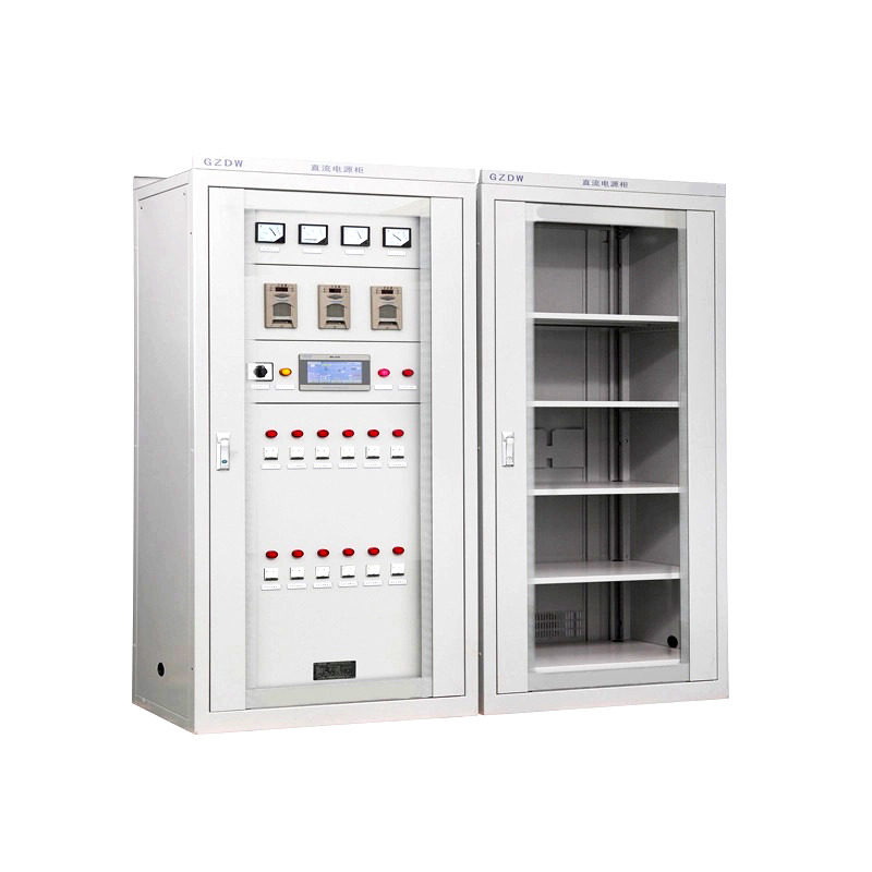
Terminology varies by industry. A compact enclosure serving a few circuits may be called a DC distribution box, while a larger floor-standing assembly may be called a DC distribution panel or cabinet. The name alone does not establish its voltage rating, protective functions, or suitability for a particular source.
How a DC Distribution Board Works
1. A DC source supplies the incoming circuit
The board receives energy from a source compatible with the connected loads. In a battery-backed system, a rectifier or charger can supply the DC bus while maintaining the battery according to the battery manufacturer's requirements. If the AC input is lost, the battery may continue supplying the DC bus, subject to the system arrangement, battery condition, and load demand.
Other installations use a dedicated DC power supply, a renewable-energy source, or a DC bus from another assembly. These sources do not behave identically. A battery can deliver substantial fault current, while some power supplies limit their output current. The protection design must account for the actual source and its operating range.
2. The incoming supply reaches the distribution bus
Inside the board, conductors or busbars carry the incoming supply to the outgoing feeder devices. The bus system must be selected for the expected current, temperature rise, short-circuit conditions, and physical arrangement. Positive and negative conductors are identified according to the design and applicable requirements.
The grounding arrangement also matters. Some DC systems intentionally connect one pole or a midpoint to ground; others are designed to operate without an intentional ground connection. The chosen arrangement affects insulation monitoring, fault detection, switching, and protection. It should be shown clearly on the system drawings rather than assumed from the enclosure layout.
3. Outgoing devices feed individual loads
From the bus, separate feeders supply relays, control circuits, communication equipment, DC motors, or other designated loads. Each feeder is selected for its cable, normal operating current, load characteristics, and possible fault conditions. A circuit schedule identifies which load each feeder serves.
When a fault occurs, a fuse or circuit breaker intended for the application should interrupt the affected circuit within the limits of its rating. The aim is to protect the circuit and, where coordination permits, avoid unnecessarily interrupting other loads. Selectivity must be checked using device characteristics and the actual fault-current range; it is not guaranteed simply because every feeder has a separate breaker.
4. Monitoring and alarms support operation
Depending on the specification, a board may provide indications for DC voltage, incoming supply status, feeder status, fuse failure, or insulation problems. Some installations also send alarms to a supervisory system. The usefulness of these features depends on where sensors are installed, how signals are configured, and whether operators know what action each alarm requires.
Monitoring does not replace inspection or testing. It provides information that helps personnel recognize abnormal conditions and plan a response before a fault affects critical equipment.
Main Components and Their Roles
| Component | Typical role | What the buyer should verify |
|---|---|---|
| Incoming isolator or breaker | Provides switching and, where applicable, protection for an incoming circuit. | DC voltage, current, pole arrangement, isolation function, and source-specific duty. |
| Positive and negative busbars | Carry current to outgoing feeders. | Continuous current, temperature rise, insulation, and short-circuit withstand capability. |
| Outgoing fuses or breakers | Protect individual circuits against applicable overcurrent conditions. | DC interrupting rating, voltage, polarity instructions, coordination, and cable protection. |
| Terminals and cable connections | Connect field cables to the assembly. | Conductor size, terminal rating, entry direction, identification, and maintenance access. |
| Monitoring devices | Indicate selected operating conditions and alarms. | Measurement range, alarm contacts, communications, and required settings. |
| Enclosure and barriers | House equipment and reduce exposure to environmental and electrical hazards. | Site conditions, ingress protection, access, ventilation, and internal segregation. |
Additional equipment may include surge protection, battery switching, rectifier modules, or insulation monitoring. These are application-dependent features, not automatic contents of every board. Confirm the scope on the single-line diagram and bill of materials.
Why DC Circuit Protection Requires Specific Attention
DC current does not have the regular current zero crossings associated with alternating current. Interrupting a DC circuit can therefore place different demands on a switching device and its arc-control system. A device marked for AC should not be assumed suitable for DC merely because its ampere rating appears adequate.
For DC circuit protection, check the manufacturer's stated DC voltage and interrupting ratings, the required number of poles, and any restrictions on connection or polarity. Some devices require poles to be connected in a particular arrangement to achieve a specified DC voltage rating. The approved arrangement may differ according to whether the circuit is grounded and where the fault occurs.
Both ends of the fault-current range deserve attention. The maximum prospective current must remain within the interrupting and withstand capabilities of the relevant equipment. At the other end, a protective device must also respond appropriately to credible lower-current faults. Cable length, source characteristics, operating conditions, and the device's time-current curve all influence that assessment.
Surge protection is a separate question from overcurrent protection. If a project requires DC surge protective devices, select them for the system voltage, grounding configuration, installation location, and applicable requirements. Coordination with upstream and downstream equipment should be reviewed as part of the overall protection design.
DC Board vs. AC Board: What Changes?
Both types distribute power to multiple circuits, but they should not be treated as interchangeable assemblies. An AC distribution board is designed around the voltage, frequency, source characteristics, and protective requirements of its AC system. A DC distribution board is designed around a DC operating range, polarity, grounding arrangement, and DC switching duty.
The distinction is especially important when a facility has both supplies. For example, an AC board may feed a rectifier, while a DC board distributes the rectifier and battery output to protection and control loads. The two boards serve related functions, but each requires components and verification appropriate to its own supply.
For a broader explanation of distribution-board functions in industrial facilities, see this industrial power distribution board guide. When discussing a DC project, specify the DC source and system requirements rather than relying on a general board description.
Where Are DC Distribution Boards Used?
Substations and power plants
Auxiliary DC supplies can support protection, control, signaling, and switching functions. A buyer should distinguish loads that must remain available during an AC failure from loads that can be interrupted. That distinction informs feeder grouping, battery sizing, alarm priorities, and the maintenance strategy.
Telecommunications and data infrastructure
DC systems may distribute power to communications and associated equipment. Important design questions include the acceptable voltage at each load, feeder length, the consequences of a circuit failure, and whether the system uses redundant sources or distribution paths.
Industrial automation and process equipment
A DC distribution panel can organize supplies for controls, instrumentation, and field devices. Designers should consider starting currents, current-limited power supplies, sensitive electronic loads, and the separation of circuits whose failure would affect different parts of a process.
Solar and battery energy systems
DC distribution equipment can also be used within photovoltaic and battery systems, but an assembly intended for one DC application is not automatically suitable for another. PV source behavior, maximum voltage under relevant conditions, bidirectional battery current, and grounding arrangements can require different components and protection methods. Specify the precise application before requesting a design.
How to Specify a Board for Your Project
Start with the load list
Record the load name, required voltage range, normal current, peak or starting current where relevant, operating duty, and required feeder count. Identify loads that operate simultaneously and those that must remain energized during a source failure. Leave an agreed allowance for future circuits if expansion is expected.
For a simple preliminary check, power in watts equals DC voltage in volts multiplied by current in amperes. A load drawing 5 A at 24 V consumes approximately 120 W at that operating point. This calculation does not determine feeder size or protection by itself: the designer must also consider actual voltage range, cable length, duty, losses, and applicable rules.
Define the source and fault conditions
Provide the nominal and maximum DC voltage, source type, source capacity, and expected operating modes. For batteries, include the proposed battery configuration and the manufacturer's relevant electrical data. For rectifiers and power supplies, provide output characteristics, current limits, and whether parallel operation is planned.
Ask the design team to establish credible maximum and minimum fault-current conditions at the board and outgoing circuits. If more than one source can feed a fault, the assessment needs to account for each applicable configuration. Confirm which devices can safely interrupt or withstand the resulting duty.
Review cable, enclosure, and site constraints
Long DC feeders can experience a meaningful voltage drop, particularly when the load is sensitive to its minimum input voltage. The cable assessment should include both conductors in the current path, the actual current and length, conductor temperature, and acceptable voltage at the load. Avoid choosing a cable solely from the outgoing breaker's nominal rating.
Specify indoor or outdoor installation, ambient conditions, dust, moisture, corrosive exposure, cable entry, and available working space. An enclosure protection rating should match the environment, but it does not by itself establish suitability for every exposure or guarantee adequate cooling.
Agree on drawings and acceptance checks
Request a single-line diagram, feeder schedule, general arrangement, component list, terminal details, and the proposed nameplate information. Also agree on the applicable assembly standard, inspection scope, routine checks, and any project-specific tests before manufacturing begins.
For a battery-backed distribution board, make the boundary between the battery, charger, and outgoing distribution explicit. Identify who supplies each item, where isolation is located, which alarms are required, and who is responsible for commissioning the complete system.
Operation and Maintenance Considerations
A well-labeled board helps operators connect a drawing to the physical equipment quickly. Feeder identifiers, source labels, polarity markings, and current drawings are particularly valuable during a fault or planned shutdown. Keep the as-built documentation available to the personnel responsible for the installation.
Maintenance should follow the equipment manufacturer's instructions and the site's electrical safety procedures. Multiple DC sources can remain energized independently, and a battery may continue to supply a circuit when the AC input is disconnected. Qualified personnel should identify all sources, isolate the relevant circuits, and verify the absence of voltage using an appropriate procedure before work begins.
Review alarm records, visual condition, ventilation, and signs of damage during scheduled inspections. Connections and protective devices should be assessed according to the manufacturer's instructions and site procedures. Any change to loads or source configuration should trigger a review of current, voltage drop, fault duty, and circuit identification.
Conclusion
A DC distribution board gives a project a structured way to route and protect individual DC feeders. Its effectiveness depends on the complete system: source characteristics, voltage range, fault current, grounding, protective-device coordination, and the needs of each load.
Before requesting a quotation from Giant Electric, prepare a load schedule and identify the operating and backup conditions that matter to your facility. That information helps the supplier and project engineer establish the right assembly boundary, protective devices, monitoring functions, and documentation for the application.
FAQs
Does a DC power distribution board convert AC into DC?
Not necessarily. Distribution is the board's central function. A rectifier or power supply performs conversion; it may be separate from the board or included in a larger integrated assembly. Confirm the scope in the quotation and drawings.
Can an AC circuit breaker be used in a DC distribution panel?
Only if the manufacturer specifically rates and permits that device for the DC voltage, current, pole configuration, and fault duty in question. An AC rating alone is insufficient evidence of suitability.
How is a battery distribution board different from a battery charger?
A charger manages the supply used to charge a battery according to the system design. A battery distribution board routes battery-backed DC power to outgoing circuits. One enclosure can contain both functions, but their ratings and responsibilities should still be identified separately.
Will a DC board keep equipment running during a power outage?
Only if the complete system includes a suitable independent or stored-energy source and is designed to supply the required loads during the outage. Runtime depends on battery capacity, condition, load profile, allowable voltage, and other system losses.
How many outgoing circuits should be included?
The number follows the load list and the desired separation of functions. Grouping all equipment on one feeder can reduce component count, but it may also enlarge the effect of a fault. Consider criticality, maintenance needs, cable routing, and future expansion.
Is a DC distribution box suitable for a solar PV system?
It may be, if it is specifically designed and rated for the PV system's maximum voltage, current, fault conditions, grounding arrangement, and applicable requirements. A generic DC label is not enough to establish PV suitability.
What information is most useful when requesting a quotation?
Provide the source details, voltage range, load and feeder schedule, available fault-current information, grounding arrangement, installation environment, required monitoring, applicable standards, and preferred drawings and test documentation.