


A industrial control panel is used when an electrical system needs a deliberate way to manage safe, maintainable control architecture for motor and process equipment. It is not simply a cabinet of components: the design has to match the source, load profile, fault conditions, installation environment, and operating objective. This guide explains the electrical logic, the practical decisions that affect reliability, and the questions an engineer should settle before releasing drawings or purchasing equipment. In project work, the most useful outcome is a system that is understandable during commissioning and remains maintainable after handover.
Key Takeaways
- Start with measured electrical behaviour and the single-line diagram, not a generic component list.
- Separate functional requirements from protective requirements; both must be confirmed before energization.
- Account for harmonics, switching duty, ambient conditions, access, and future expansion early in the design.
- Use test records and settings documentation to make later troubleshooting faster and safer.
What the Industrial control panel Does
The essential job is to receive electrical energy at one point, control or route it through deliberately selected paths, and protect connected circuits when conditions move outside the design envelope. The exact arrangement varies by application. A plant with continuous process loads has different priorities from a photovoltaic site, a battery room, or a building with standby generation. In every case, a clear single-line diagram establishes the source, the isolation points, the protective devices, and the downstream boundaries of responsibility.
For projects needing related low-voltage equipment, Zhejiang Zhegui Electric Co., Ltd. provides motor control center panel. The product choice should follow the project specification and verified duty; it should not be based only on physical size or the number of outgoing ways.
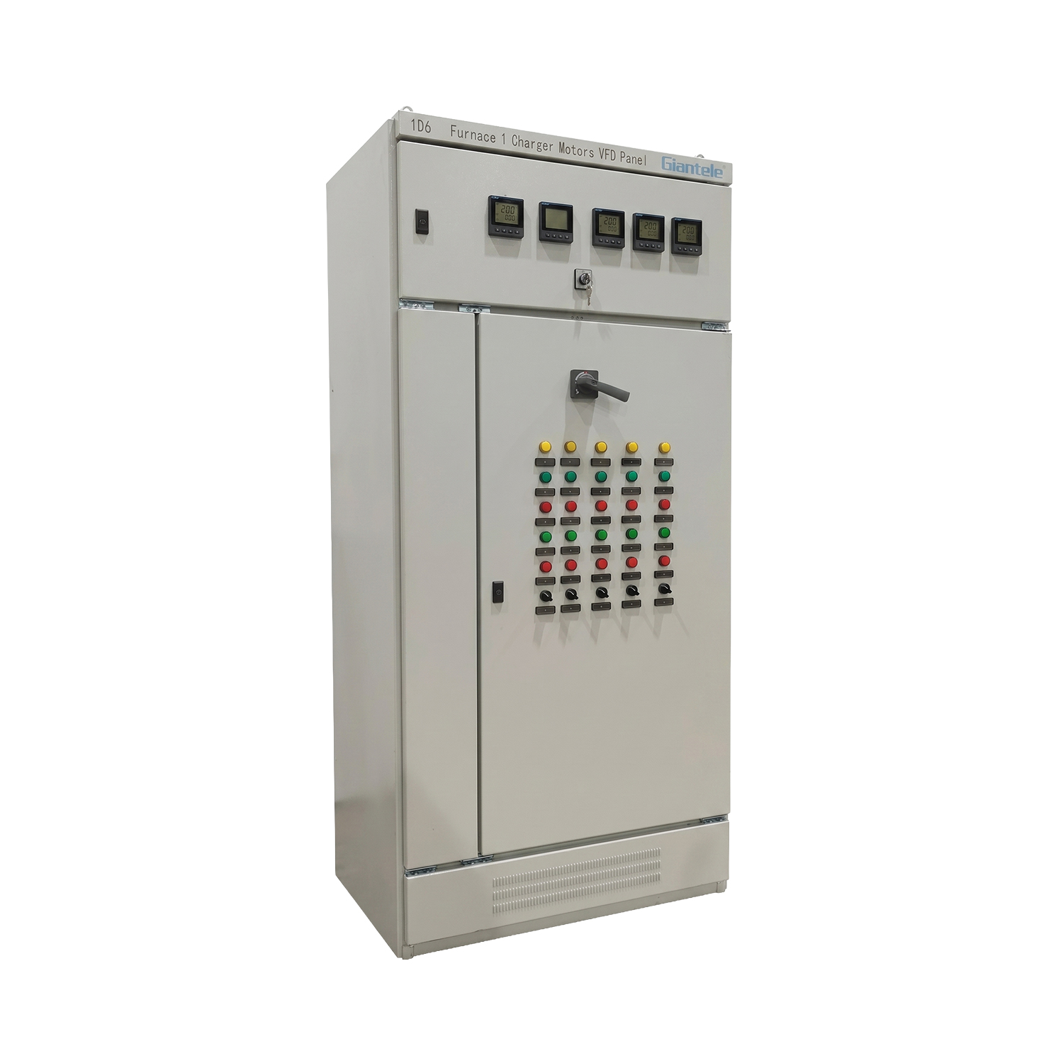
How the Electrical Process Works
Electrical equipment works predictably when current has a defined source, a rated path, and a coordinated protective response. Incoming conductors connect through an isolating and protective device. Internal conductors or busbars distribute the supply to functional sections. Each outgoing circuit is then controlled, protected, and identified according to its load. Monitoring, metering, and control devices provide the operator with enough information to identify abnormal loading without treating a normal operating change as a fault.
The practical design question is not merely whether a device can carry nominal current. It is whether it can make, break, withstand, and protect under the prospective conditions at its installation point. That requires the designer to review voltage, frequency, prospective short-circuit current, conductor method, duty cycle, temperature, ventilation, pollution, vibration, and access. A component can be correctly rated in isolation yet unsuitable in the assembled system when those conditions are ignored.
Engineering Inputs to Confirm Before Design Freeze
| Input | Why it matters | Decision it supports |
|---|---|---|
| Single-line diagram and source data | Defines supply arrangement, earthing approach, and available fault level. | Main device rating and protection coordination. |
| Load schedule and operating profile | Shows continuous, cyclic, motor, electronic, and future loads. | Capacity, feeder arrangement, and control strategy. |
| Power-quality measurements | Reveals harmonics, unbalance, transients, and reactive demand. | Need for detuning, filtering, or dynamic compensation. |
| Site environment and installation method | Affects heat dissipation, enclosure selection, corrosion risk, and maintenance access. | Mechanical arrangement and derating. |
| Owner operating philosophy | Clarifies alarm, manual override, redundancy, and isolation expectations. | Control logic and maintainability. |
Design Approach: Function First, Then Protection
Begin by describing what each section must do in normal service. A distribution section may feed circuits; a motor section may start, stop, and protect drives; a compensation section may respond to changing reactive demand. Only then select the components and wiring paths that deliver that function. This sequence reduces the common mistake of assembling parts first and discovering later that the panel cannot be tested, isolated, or expanded without disrupting an adjacent circuit.
Protection must be coordinated as a system. Upstream and downstream devices should be reviewed for their operating characteristics, the available fault duty, and the desired discrimination. Equipment labels should identify source and load, while drawings should identify terminal numbers, conductor references, device tags, and the location of any remote interlocks. Zhejiang Zhegui Electric Co., Ltd. can use project data such as a load list and single-line diagram to discuss a configuration, but final selection should remain subject to the project engineer's verification.
Harmonics, Switching, and Thermal Limits
Modern facilities often combine motors, drives, rectifiers, UPS equipment, welders, or inverters. These loads can alter waveform shape and change the stress experienced by capacitors, conductors, breakers, and transformers. A correction or distribution design therefore needs a power-quality review before a conventional configuration is copied from another site. In an appropriate application, automatic transfer switch panel or low-voltage distribution boards can be considered as part of the wider system rather than as an afterthought.
Thermal performance is equally practical. Heat is generated by conductors, protective devices, coils, electronics, and connections. The enclosure has to dissipate it under the actual ambient condition, and installers need access to torque, inspect, and replace components. Tight layouts may look economical on a drawing but can increase temperature and make routine maintenance difficult. Allowing realistic cable space and access at the design stage is usually cheaper than reworking a live installation.
Selection and Review Framework
Use the following sequence when comparing options. First, identify whether the electrical problem is steady, intermittent, or rapidly changing. Second, determine whether it is caused by real power demand, reactive demand, waveform distortion, voltage variation, or an operational constraint. Third, select an arrangement that performs the required function without adding an unmanaged risk. Finally, define the acceptance tests and the records that must be delivered with the assembly.
For a new installation, review future feeders, spare physical space, and control terminals separately. A spare breaker position is not automatically a usable future circuit if the busbar, cable route, short-circuit rating, heat load, or control supply has not been considered. Clear expansion assumptions are more valuable than an arbitrary percentage of spare ways.
Installation, Testing, and Handover
Installation should follow approved drawings and safe work procedures. Before energization, check mechanical fixing, earthing continuity, conductor identification, lug torque, phase sequence where relevant, insulation resistance as permitted by the connected equipment, protective-device settings, and control interlocks. Do not use commissioning as a substitute for design review. Energize in a controlled sequence, observe normal operating values, and record any settings that an operator must understand.
Handover documentation should include the as-built single-line diagram, wiring diagrams, bill of materials, test records, device settings, controller parameters, maintenance instructions, and a list of replaceable items. These records turn an assembly into an operating asset rather than an unknown black box. Giant Electric's related product pages can be useful when defining the equipment scope, but site personnel should keep their own verified project records.
Common Errors and How to Avoid Them
Three errors recur across electrical projects. The first is sizing only for an average load while ignoring switching events, starting current, harmonic content, or future demand. The second is treating a protective device as a universal solution without checking coordination and fault duty. The third is overlooking maintenance: no safe isolation point, no space to terminate cables, unreadable labels, or settings stored only in an installer’s memory. A structured design review identifies these issues before equipment arrives at site.
Another avoidable error is using a solution designed for one electrical phenomenon to solve another. For example, reactive-power correction does not automatically remove harmonic distortion, and a filter selected without measurement can create an unsuitable response. Identify the condition first, measure it where possible, and then decide whether the right answer is a change in operating practice, a conventional correction stage, a detuned arrangement, an active device, or no additional equipment at all.
EU Compliance Context for Industrial Control Panels
Where an industrial control panel is made available on the EU market, the applicable legal assessment should start with the actual product configuration and intended use. For electrical equipment within its voltage scope, Directive 2014/35/EU (the Low Voltage Directive) addresses health and safety objectives. Its stated voltage range is 50 V to 1,000 V AC and 75 V to 1,500 V DC. Directive 2014/30/EU (the EMC Directive) addresses electromagnetic emissions and immunity. Whether either directive applies, and how the technical file is structured, should be confirmed for the completed assembly rather than assumed from a component list.
CE marking is the visible result of the applicable conformity-assessment process; it is not, by itself, a third-party product certificate. For relevant low-voltage switchgear and controlgear assemblies, use the European standard references published for the applicable EU legislation. EN 61439-1 covers general requirements for low-voltage assemblies, while EN 61439-2 covers power switchgear and controlgear assemblies. Use the current cited version and any applicable national implementation when preparing a project compliance plan. This article intentionally names EU directives and EN standards only; it does not claim that any specific Giant Electric product is CE-marked or compliant without project-specific evidence.
Application Context and Decision Boundary
For safe, maintainable control architecture for motor and process equipment, do not start with the assumption that a larger assembly will solve a poorly defined electrical issue. A useful review separates three questions: what the process requires during normal operation; what happens when a source, feeder, or component changes state; and what evidence is available from measurements or operating records. The answers define the required response time, the acceptable interruption, and the protection needed around the function. They also show whether the design needs a fixed arrangement, staged control, or a faster electronic response.
Consider a measured baseline before and after commissioning. Record line voltage, current, loading balance, temperature at accessible terminations, controller status, and any relevant quality indicators under normal representative production. The baseline does not replace formal testing, but it makes later changes easier to assess. If the operating conditions change—for example, additional drives, a new transformer, or a different generation source—repeat the review instead of assuming the original settings remain suitable. This disciplined approach helps keep the industrial control panel aligned with its actual duty.
The review should also assign responsibility at each interface. Identify who provides source data, who validates settings, who controls the switching sequence, and who accepts test results. This avoids gaps between equipment supply, installation, and operation. Agree the normal operating state, alarm response, isolation procedure, and return-to-service checks before the site is live. When those simple arrangements are documented, operators can make routine decisions without compromising the original engineering intent.
Conclusion
A well-specified industrial control panel makes an electrical system easier to operate, protect, and maintain because its purpose is visible in the design. The sound approach is to start with verified data, define the operating objective, check protection and power quality together, and plan commissioning before fabrication. Zhejiang Zhegui Electric Co., Ltd. offers related distribution and power-quality equipment, while the final assembly should always be matched to the project's documented electrical and site conditions.
FAQs
What information is needed to specify a industrial control panel?
Provide the single-line diagram, source voltage and frequency, load list, available fault data, site environment, installation location, required control functions, and applicable project standards. Power-quality measurements are important when nonlinear loads or reactive-power issues are suspected.
How is a industrial control panel different from a standard enclosure?
An enclosure is primarily a mechanical housing. A complete assembly includes the electrical paths, protective devices, control functions, labels, testing, and documentation needed to perform a defined system duty safely.
When should harmonics be assessed?
Assess them before selecting correction or filtering equipment when the site has drives, rectifiers, inverters, UPS systems, welding loads, or unexplained heating and nuisance trips. Measurements should be taken under representative operating conditions.
Can the system be expanded later?
Often yes, but expansion should be designed rather than assumed. Check physical space, busbar capacity, fault rating, thermal margin, cable routes, control terminals, and the settings of upstream protective devices.
What should be recorded during commissioning?
Keep inspection and functional-test records, measured operating values, protection settings, controller parameters, as-built drawings, and any deviations approved during commissioning. These records support future maintenance and fault finding.