


A capacitor bank is not one universal product. In an AC plant, it may supply reactive power to improve power factor and release capacity in cables and transformers. In a drive or converter, a DC-link capacitor bank smooths a DC bus and supports transient energy exchange. Both use capacitors, but their duty, selection method, protection, and failure modes differ. This guide separates those applications and shows how a sound sizing decision is made from measurements and engineering constraints—not from a nameplate guess.
Key Takeaways
- First identify whether the duty is AC reactive-power compensation or DC-link energy storage; the calculations are not interchangeable.
- Size AC PFC from active power and measured starting and target power factor, then design the switching steps around load variation.
- Assess harmonics before ordering capacitors; a detuned reactor may be needed to reduce resonance risk.
- For DC links, select capacitance, voltage, ripple-current capability, temperature, and lifetime for the converter duty cycle.
Define the capacitor bank duty
AC power-factor correction aims to reduce the reactive current drawn from the source by supplying reactive power locally. It can be fixed for a stable load or automatically stepped when the load changes. The desired outcome is not simply a high reading on a meter; it is a stable operating point that respects utility requirements and avoids leading power factor at light load.
A DC-link capacitor bank has a different role. It filters the rectified DC supply and helps the converter maintain a suitable DC-bus voltage during switching and load changes. Its ripple-current and thermal duties can be severe. Treating a DC-link requirement as though it were an AC kVAr correction problem is a fundamental specification error.
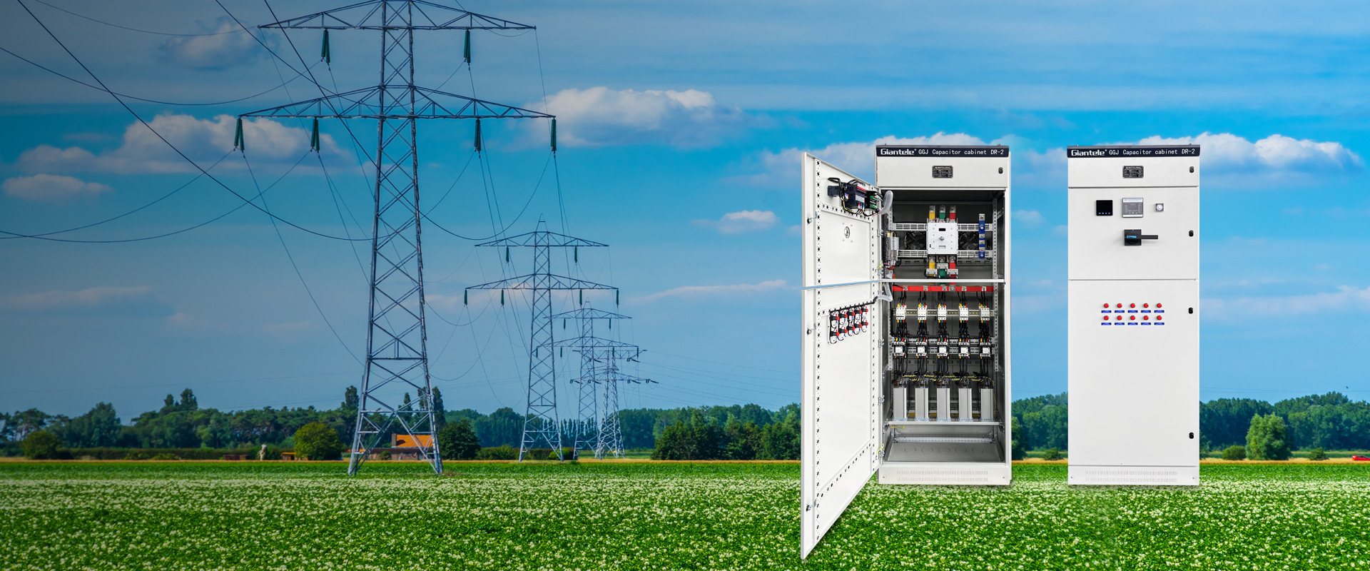
How to size AC reactive power compensation
Measure the real operating condition rather than relying on an annual bill. Record active power in kW, present power factor, operating hours, load variation, voltage, and harmonic spectrum. The basic relationship is: required kVAr = kW × (tan arccos present power factor − tan arccos target power factor). The calculation is a starting value, not a complete panel design. It must be reviewed with the actual load pattern, transformer capacity, and whether a utility target permits a particular leading or lagging band.
| Load pattern | Typical compensation approach | Design caution |
|---|---|---|
| Stable inductive load | Fixed capacitor bank | Verify that the load remains on when the bank is connected. |
| Shift-based or varying load | APFC panel with steps | Choose step ratios that track demand without excessive switching. |
| High nonlinear-load content | Detuned capacitor bank or other power-quality solution | Study harmonics before finalising reactor tuning. |
| Fast-changing reactive demand | Dynamic compensation such as SVG, where appropriate | Evaluate response time and network conditions. |
The published power factor correction solutions page distinguishes fixed capacitor banks, APFC, and SVG by load behaviour. That is the correct purchasing sequence: determine the behaviour of the reactive load first, then select the technology. A fixed bank on a variable load can overcorrect when equipment is off; too few APFC steps can cause a controller to hunt around its target.
Harmonics change the design
Modern plants often include drives, UPS systems, welding equipment, rectifiers, and other nonlinear loads. Capacitors can interact with network inductance, creating resonance that increases capacitor current or voltage stress. A detuned reactor is placed in series with capacitor steps to shift the resonant point and limit amplification. The required detuning is an engineering decision based on the measured spectrum and network model, not a standard add-on percentage.
Giantele notes that its detuned reactor is intended where harmonics affect compensation performance. Provide power-quality measurements, transformer data, existing capacitors, and the expected drive or inverter population to the reviewing engineer. A harmonic issue may require a detuned bank, an active filter, changes to drives, or a combination; a capacitor bank alone is not a universal harmonic filter.
DC-link capacitor bank considerations
For a DC link, the voltage rating must include the actual bus voltage and expected transients. Ripple-current capability, equivalent series resistance, cooling, physical connection inductance, discharge arrangement, and lifetime at temperature all deserve attention. Paralleling units may increase capacitance and ripple-current capability, but current sharing, fusing, busbar layout, and equal connection lengths influence the result. Follow the capacitor and converter manufacturer application data for the relevant topology.
Industrial use cases often mix the two meanings of capacitor bank. A VFD cabinet may contain a DC link, while the facility’s main bus may use an APFC panel. They address different points in the system and should be studied separately. Do not remove or add DC-link capacitors as a site power-factor correction measure, and do not use a facility kVAr calculation to specify a converter’s DC-link hardware.
Protect, monitor, and maintain the bank
An AC bank generally needs appropriate isolating and protective devices, switching equipment suited to capacitor duty, discharge provisions, controller logic where stepped, ventilation, and clear labels. The design should consider inrush, restrike, overvoltage, capacitor tolerances, and temperature. Correctly applied capacitor contactors matter when frequent switching is expected. Giantele’s CJ19 capacitor contactor page is relevant product context for that switching duty.
Maintenance should compare measurements to commissioning baselines. Look for swelling, leakage, damaged terminals, heat discoloration, fan failures, loose connections, failed fuses, abnormal sound from reactors, and drift in capacitance or power factor. De-energise, discharge, verify absence of voltage, and follow approved procedures before touching the assembly. Repeated fuse operation is a diagnostic signal, not a reason to fit a larger fuse.
Conclusion
A capacitor bank becomes reliable when its purpose is clear and its components are selected for the real electrical environment. Separate AC PFC from DC-link duty, measure the load, evaluate harmonics, choose step structure and protection, and document commissioning values. Zhejiang Zhegui Electric Co., Ltd. can use that engineering input to align a capacitor-bank, APFC, reactor, or dynamic solution with the installation.
FAQs
How do I calculate a capacitor bank size?
For AC PFC, use measured kW and present and target power factor in the kVAr relationship shown above, then validate the result against load variation and harmonic conditions.
What is the difference between a capacitor bank and an APFC panel?
A capacitor bank may be fixed. An APFC panel uses a controller and switching steps to connect or disconnect capacitance as the load changes.
When is a detuned reactor needed?
It is considered when harmonic-producing loads or a network study indicate resonance or capacitor stress risk. Selection follows measured data and engineering review.
Can one capacitor bank solve all power-quality problems?
No. It can address reactive-power duty when properly designed, but voltage dips, harmonic distortion, unbalance, and transient issues may require different measures.
Are DC-link capacitors used for power factor correction?
They serve the converter DC bus. Facility power-factor correction is a separate AC-system function.