


Power Distribution Boards work best when they are treated as a project process rather than a last-minute purchase. The process starts with sources and loads, moves through protection and construction decisions, and continues with installation, commissioning, records, and maintenance. Skipping a step can create expensive corrections: an incomer may not match the source, cables may not fit, spare ways may be unusable, or protective devices may not coordinate as intended. This guide gives a practical sequence for project teams while keeping responsibility for detailed electrical design with qualified professionals.
Key Takeaways
Start with a current single-line diagram and load schedule, not a product catalogue.
Determine normal current duty and short-circuit duty separately.
Specify the enclosure, cable entries, access, protection, metering, and documentation before manufacture.
Commission against approved procedures and keep records current through the board’s life.
Step 1: Define the source and load schedule
Identify exactly what will feed the board: utility transformer, generator, upstream board, or source-transfer arrangement. Record voltage, frequency, phase arrangement, earthing system, expected supply characteristics, and any operating modes. Then list every outgoing feeder and its destination. The load schedule should distinguish continuous, intermittent, motor, heating, lighting, IT, critical, and future loads where relevant.
Distribution board sizing begins with credible data. A planning relationship is: estimated demand = sum of applicable load demands after approved diversity assumptions. It is only a design aid; the responsible engineer must select assumptions that fit the installation and applicable rules. Starting currents, non-linear loads, generator constraints, and future expansion can change the result.
Step 2: Establish rating and short-circuit requirements
Choose current ratings for the incomer, busbars, and outgoing circuits using the approved load study and installation conditions. Then separately determine the prospective short-circuit current at the board location. The fault study informs device interrupting capability and the assembly’s required withstand performance. A board cannot be validated by normal current alone.
Step-by-step decision record
Step | Required output | Why it is needed |
|---|---|---|
1 | One-line diagram and source data | Defines the board’s position and source arrangement |
2 | Load schedule and demand basis | Establishes incomer, busbar, and feeder duties |
3 | Fault-level and protection study | Defines short-circuit and coordination requirements |
4 | Construction brief | Confirms enclosure, access, cable routes, separation, and metering |
5 | Approved drawings and test plan | Controls manufacture, installation, and handover |
6 | As-built records and maintenance plan | Keeps the board safe and understandable in use |
Step 3: Select the board construction
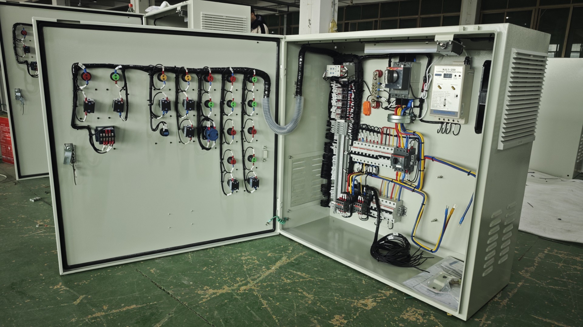
Describe the site environment in usable terms: indoor or outdoor, ambient conditions, dust, moisture, corrosion, washdown, sunlight, vibration, and available space. State the required enclosure performance and mounting arrangement. Confirm cable entry direction, conductor sizes, termination needs, bend space, gland plates, and any busway or generator interface. Decide what level of internal separation and access is needed for the facility’s maintenance strategy.
At this stage, select protective devices and any metering or communication functions as part of the complete system. Ask the manufacturer to confirm manufacturability against the drawings. A power distribution board manufacturer’s product information can identify available categories, but it cannot replace the project brief.
Step 4: Review drawings and verification evidence
Review the general arrangement, single-line diagram, device schedule, terminal arrangement, cable entry, nameplates, and circuit directory before release. Make sure all parties are working from the same revision. If EN IEC 61439 is specified, ask what evidence and routine checks apply to the delivered configuration. Be precise about responsibility for engineering, assembly, installation, testing, and acceptance.
Zhejiang Zhegui Electric Co., Ltd. can support an agreed board design. Procurement teams should ensure that any approved change—such as a new device, cable direction, metering function, or source arrangement—is evaluated before it is built, not after delivery.
Step 5: Install and commission correctly
Installation is not merely fixing the enclosure to a wall or floor. The board must be supported, earthed, protected from unsuitable exposure, connected with appropriate conductors, and accessible for operation. Qualified personnel should torque connections to the relevant instructions, identify circuits, and complete the approved inspection and test programme. The commissioning package should match the project’s local rules and design documents.
Before energisation, verify that labels match circuits, protective-device settings are recorded, covers and barriers are in place, and the intended source arrangement is understood. During initial operation, investigate unexpected trips, heat, noise, or alarm indications rather than treating them as normal. Giant Electric’s guide to distribution-board testing is a useful starting point for setting questions about factory and site acceptance; the site team must define the actual test scope.
Step 6: Maintain the circuit directory and board condition
A circuit directory becomes unreliable quickly when changes are made without documentation. Update it whenever a circuit’s destination, rating, or protective arrangement changes. Keep the as-built one-line diagram, test records, settings, and equipment information where authorised users can access them. Set inspection intervals according to environment, load, criticality, and regulatory requirements. Look for damaged labels, water or dust ingress, discoloration, loose connections, corrosion, unusual heat, and recurring protective operations.
Giant Electric can provide equipment built for the agreed duty, while the owner’s operating team protects long-term value by preserving design information and using a planned maintenance approach.
Conclusion
The step-by-step route to successful Power Distribution Boards is straightforward in principle: understand the source and loads, calculate normal and fault duty, specify construction, review the design, install and test carefully, then maintain the records and equipment. The discipline lies in completing every step with real project data. That is what makes a board safe, workable, and ready for future change.
FAQs
What information is needed to size a distribution board?
At minimum, provide source voltage and arrangement, load schedule, demand basis, fault level, outgoing feeders, environmental conditions, cable route, access constraints, and any protection, metering, or expansion requirements.
Is a load schedule enough to select breakers?
No. Breaker selection also depends on conductor capacity, fault level, load characteristics, coordination, settings, and applicable rules. A qualified designer should confirm the complete protective scheme.
Why should cable entry be specified early?
Cable direction and size affect enclosure dimensions, gland plates, termination space, bend radius, access, and internal layout. Late changes can make an otherwise suitable board difficult to install.
What is protection coordination?
It is the planned relationship between protective devices so they respond safely and, where required, selectively to faults. It is established through engineering review, device data, and system conditions.
What records should be kept after commissioning?
Keep as-built drawings, circuit directories, protection settings, test and inspection records, device information, maintenance records, and controlled documentation of every later modification.