


A shunt capacitor bank is connected in parallel with the power system to supply capacitive reactive power. It is widely used for power factor correction and can support voltage conditions when designed for the network. The word “shunt” describes the connection, not a simplified safety case: capacitors, switching devices, fuses, relays, reactors, cables, and controls must operate as one coordinated assembly. This article outlines application principles and the protection questions that project engineers and operators should resolve before energization.
Key Takeaways
Protection begins with a correct application: voltage, configuration, grounding, harmonics, fault duty, and switching duty must be defined together.
A shunt capacitor bank can improve reactive-power balance, but its output changes with voltage and it must not be applied without considering system disturbances.
Bank protection commonly addresses external faults, internal component faults, abnormal current or voltage, and unbalance conditions appropriate to the design.
Settings and hardware must be verified by qualified engineers using the approved system study, applicable EU-market requirements where relevant, and manufacturer instructions.
What Makes a Shunt Capacitor Bank Different?
Connected in parallel, a shunt capacitor bank supplies reactive power into the bus or feeder where it is installed. For an inductive system, that local capacitive contribution can reduce reactive current drawn from the upstream source. In distribution networks, the possible outcomes include improved power factor, reduced current in selected equipment, and support for voltage regulation. The actual result depends on the network impedance, operating voltage, bank location, and the load profile.
Capacitor reactive output is voltage-dependent. In simplified form, reactive power varies approximately with the square of applied voltage. This means a bank provides less reactive support when voltage falls, even though that may be a time when the network needs support. It also means overvoltage, switching transients, and harmonic distortion require thoughtful design. A capacitor bank must never be treated as an unrestricted source of correction under every system condition.
The application begins by defining whether the bank is low-voltage or medium-voltage, fixed or switched, grounded or ungrounded as applicable to its configuration, and installed as a standalone correction unit or as part of a filter. The allowable system-voltage range, frequency, insulation level, fault duty, feeder configuration, and protective coordination all influence the final arrangement.
Configuration and Application Principles
Capacitor units are arranged in series-parallel groups to achieve the required voltage and reactive-power rating. The bank configuration affects how internal failures and unbalance can be detected. Some arrangements use grounded-wye connections; others use different configurations to meet system and protection objectives. The correct configuration is selected through the system design, not by a generic preference.
For industrial low-voltage power factor correction, staged banks are often controlled by a relay that reads voltage and current through CTs. For substation and feeder applications, switching and protection schemes may involve breakers, relays, voltage sensing, current sensing, and supervisory control. In either case, the initiating principle is the same: the bank must enter and leave service in a way that is electrically safe, coordinated with the network, and appropriate for the connected capacitors.
Protection objective | What it addresses | Design evidence needed |
|---|---|---|
Overcurrent and short-circuit response | Fault current and abnormal current through conductors, devices, or bank sections. | Fault study, equipment ratings, conductor data, and coordination curves. |
Overvoltage / undervoltage response | Voltage conditions that can overstress equipment or indicate unsuitable operating states. | System voltage range, transient assumptions, and manufacturer limits. |
Unbalance detection | Changes in the bank that can indicate failed elements, units, or unequal section condition. | Bank configuration, neutral or bridge sensing method, and approved setting calculation. |
Harmonic and resonance management | Excess distortion or unfavorable system interaction with capacitors. | Power-quality measurements and harmonic or impedance study. |
Switching and discharge control | Inrush, restrike, reconnection, and stored-energy risks. | Switching-device data, discharge requirements, and operating sequence. |
Protect the Bank and Protect the System
The protection philosophy has two directions. First, it should detect internal conditions that could damage capacitor units, connections, or the enclosure. Second, it should prevent the bank from worsening external system events or remaining connected during conditions where operation is unsuitable. The exact protective devices and relay functions are project-specific. A protection engineer should select and set them from approved studies, applicable EU-market requirements where relevant, and manufacturer instructions; a blog article cannot provide universal settings.
Individual capacitor fusing, bank fuses, circuit breakers, and protective relays may all have roles, depending on the design. Their coordination should consider energization inrush, normal capacitor current, harmonic current, back-to-back switching where relevant, and available fault current. A protective device that is too sensitive may create nuisance outages; one that is too slow or inadequately rated may fail to clear a damaging condition. Both outcomes are design failures, not merely maintenance concerns.
Unbalance protection is especially linked to configuration. A failed capacitor element or unit can alter the voltage or current distribution in a series-parallel group. Measuring an appropriate neutral, bridge, or differential condition can provide an early indication, but the measured quantity and alarm/trip threshold must reflect the actual bank arrangement. Changes to capacitor units or wiring after commissioning should trigger a review of that scheme.
Harmonics, Detuning, and Switching Risks
Harmonic review is central to capacitor bank protection because capacitors can change the network’s impedance characteristics. A system with variable-speed drives, rectifiers, arc equipment, or other nonlinear loads may experience higher harmonic current or a resonance condition after capacitor installation. The risk cannot be assessed from the capacitor rating alone. Collect representative measurements and, where warranted, perform a harmonic study that includes source impedance, transformer data, existing capacitors, and the proposed bank.
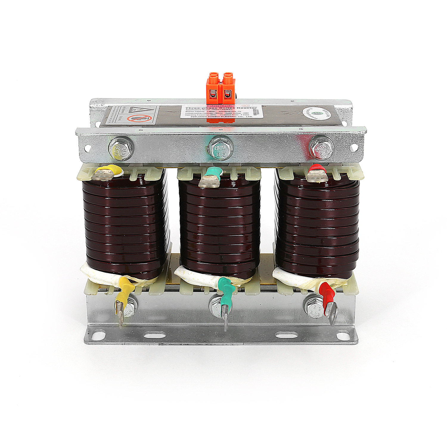
A detuned reactor harmonic filter reactor can form part of a coordinated detuned solution. It is selected with the capacitors so the intended tuning, voltage stresses, losses, and thermal performance are understood. Zhejiang Zhegui Electric Co., Ltd. lists this product category under Giantele; suitability for a specific bank must be determined by the project engineer and validated against actual system data.
Switching itself produces transients and inrush. These effects are influenced by the network, capacitor size, whether another bank is already energized, and the switching technology. The switching device should be chosen for the duty and coordinated with any inrush-limiting, pre-insertion, or control arrangements specified by the design. A CJ19 low-voltage power capacitor contactor is one relevant product category for capacitor-switching applications. A disconnected capacitor requires time and an approved discharge path before safe maintenance or reconnection. Operators should not override those times to solve a short-term power-factor alarm.
Low-Voltage Automatic Banks: Control and Protection Together
In a low-voltage automatic system, the controller, CT arrangement, stages, switching devices, and protection need to agree. The CT must measure the intended load and preserve correct polarity and phase relationship. The controller needs the correct CT ratio, voltage reference, target power factor, stage values, delays, and alarm limits. A correctly selected bank can still behave badly if these inputs are wrong.
A Giantele APFC panel is intended for automatic power-factor-correction applications, while the installation must still follow the approved drawings and product documentation. Test each stage under controlled conditions, verify the protective indications, and observe whether the controller removes compensation when inductive load declines. No setting should be accepted solely because it was supplied as a default.
Commissioning Checks Before Placing the Bank in Service
Commissioning should confirm the physical installation and the intended protection behavior. Begin with documented isolation and stored-energy safety procedures. Verify nameplates, ratings, earthing, clearances, ventilation, mechanical connections, device labels, conductor identification, and approved drawing revisions. Review whether site changes since design—such as a new drive system or different transformer—alter the original assumptions.
Then validate measurement circuits, CT ratio and orientation, voltage inputs, phase relationship, controller or relay settings, trip and alarm circuits, communications, and switching sequence. For automatic systems, observe operation over a range of loads. For protection schemes, test using the approved procedure and record results. Compare actual measurements with expected response and investigate any mismatch before normal service. A complete record should include final settings, test values, wiring references, equipment serial information, and the responsible approvers.
Maintenance Signals That Deserve Attention
Unexpected alarms, repeated fuse operation, contactor wear, high temperature, unusual noise, discolored terminals, swelling components, drift in power factor, or a change in harmonic readings warrant investigation. Do not repeatedly reset a tripped bank without identifying the initiating condition. The cause could be a component issue, connection problem, changed load, distorted supply, unsuitable settings, or an external fault event.
Regular maintenance should follow manufacturer guidance and site procedures. It usually includes visual inspection, cleaning and ventilation checks, review of protective records, confirmation of mechanical connections using the approved method, and trend review. The task should be performed by qualified personnel with controls for isolation and capacitor discharge. Giantele equipment, like any power-factor-correction assembly, benefits from a maintained documentation trail that connects field findings to the original design.
Document the Protection Philosophy
A concise protection narrative is valuable at handover. It explains the intended operating states, what each alarm or trip is meant to detect, which device isolates the bank, what conditions block reconnection, and who reviews abnormal events. It should reference the approved drawings and study results rather than restating only equipment labels. This helps operators respond consistently when a control room reports an alarm late at night or after a process change.
The documentation should distinguish between an alarm that calls for inspection and a trip that demands investigation before reset. Include the approved test interval, event records to retain, and the circumstances that trigger an engineering review, such as repeated operation, changed harmonic data, altered transformer impedance, or an added nonlinear load. Protection is strongest when its operating intent remains clear after the original project team has moved on.
Coordinate With the Wider Electrical Protection System
The capacitor bank is part of a larger protection hierarchy. Its isolating device, feeder protection, transformer protection, and upstream breakers or relays should operate selectively according to the approved coordination study. A trip at the bank should not unnecessarily remove a healthy production area, and an upstream fault should not expose the capacitor equipment beyond its ratings. These relationships are evaluated through formal system studies and field verification, not inferred from device size alone.
Communication and supervisory signals deserve the same attention. If a bank is interlocked with generator operation, load shedding, a bus-tie state, or a power-management system, test the logic under the permitted commissioning procedure. An otherwise correct bank can become inappropriate if a control signal leaves it connected in an unintended operating mode. Keep the final logic diagram with the protection record.
Conclusion
Shunt capacitor bank application and protection should be designed as one coordinated task. Define the network conditions, choose a configuration that supports the objective, evaluate harmonics and switching duty, and use protection that can distinguish normal operation from damaging events. The central principle is disciplined verification: measured system data informs selection, approved studies inform settings, and commissioning proves that the capacitor bank behaves as intended in the real electrical system.
FAQs
What is a shunt capacitor bank used for?
It is connected in parallel with a power system to supply capacitive reactive power. Typical applications include power factor correction and support for voltage conditions, subject to system design and operating constraints.
Why does a capacitor bank need unbalance protection?
In applicable bank configurations, internal capacitor failures can change the balance of voltage or current between sections. Unbalance measurement can provide an alarm or trip indication when designed and set for that configuration.
Can overcurrent protection be sized from the capacitor nameplate alone?
No. It must account for the system, bank configuration, inrush, harmonic current, available fault current, device ratings, and coordination. A qualified engineer should determine the protective scheme.
What is the role of a detuned reactor in a capacitor bank?
It is used in coordinated designs to manage harmonic interaction and resonance risk. The reactor and capacitor values must be selected together from power-quality and system information.
What should be tested during capacitor bank commissioning?
Testing should cover installation condition, ratings, earthing, measurements, CT polarity and ratio, settings, alarms, trips, switching sequence, and behavior under representative load conditions, following the approved commissioning procedure.