


Efficient power systems depend on more than reducing energy use at a machine. They also depend on how effectively the distribution network carries the required power, holds voltage within acceptable operating conditions, and responds to fluctuating reactive demand. A capacitor bank is one of several tools used to improve this balance. The right solution may be a simple fixed arrangement, an automatically switched panel, a detuned design, or a dynamic system combined with filtering. This guide provides a decision framework for choosing among them.
Key Takeaways
- Start with a system objective: tariff power factor, feeder capacity, voltage regulation, process stability, or a combination.
- Match the response method to the speed and range of reactive-load change.
- Use power quality monitoring to identify harmonic and imbalance conditions before selecting capacitor equipment.
- Evaluate a solution by measured operation across load states, not only its nominal kvar rating.
Define “Efficient” for the Electrical System
For a process engineer, efficiency may mean more output per unit of energy. For a facilities team, it may mean lower avoidable charges, fewer voltage-related trips, or capacity headroom in a transformer. A capacitor bank supports these aims by reducing reactive current flowing through selected upstream equipment. The benefit is most direct where poor power factor is a material contributor to apparent-power demand, heating, voltage drop, or tariff treatment.
That definition prevents a common mistake: selecting compensation solely to reach a target number on a monthly bill. A system can meet an average power factor yet still experience voltage movement, harmonic distortion, phase imbalance, or fast reactive swings that affect sensitive equipment. Conversely, a rapidly varying load may not be served well by large, slow mechanical steps. A complete objective links the power-factor target to the actual operating problem and measurement point.
A Solution Ladder for Reactive Power Needs
Use the simplest solution that is technically suitable, but do not simplify away known power-quality risks. A stable, largely inductive base load may be a good candidate for fixed or regularly switched capacitors. A plant whose motor load changes by production step may require an automatic power factor correction panel with appropriately graduated stages. Loads with sharp reactive changes, such as some hoisting, rolling, or cyclic industrial duties, can require faster compensation. The Giantele intelligent active static var generator panel is intended for high-speed reactive-power management and is offered in 400 V configurations on the product page; confirm capacity and site requirements during design.
Where harmonics are an identified issue, compensation must be considered with filtering. Capacitors can interact with network inductance, so a selection that solves one reactive-power problem may aggravate distortion if it is not coordinated. An active harmonic filter panel addresses a different but related objective: managing harmonic current while supporting overall power quality. The appropriate combination follows measurements and engineering review, not a generic product pairing.
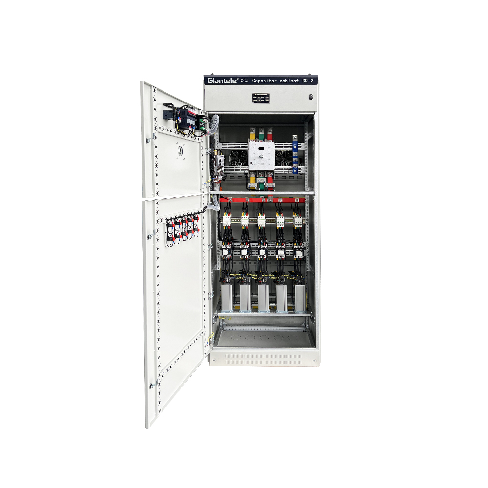
Decision Framework: Match Conditions to the Approach
| Observed condition | Decision question | Potential direction |
|---|---|---|
| Stable inductive load, little harmonic distortion | Will a fixed value remain appropriate throughout normal operation? | Fixed or limited-stage capacitor bank after protection and location review. |
| Load changes between shifts or equipment groups | What step sizes will follow demand without overshoot? | Automatic stepped correction with controller, CTs, and suitable switching. |
| Fast cyclic reactive demand | Can mechanical stages follow the required response without excessive switching? | Assess dynamic reactive-power compensation. |
| Nonlinear loads and elevated distortion | Is there a resonance risk or a need for harmonic-current reduction? | Perform a harmonic study; consider detuned or active filtering strategies. |
| Unequal phase loading | Does the solution need phase-by-phase measurement or correction? | Assess equipment capability and the cause of imbalance before selection. |
This framework is intentionally diagnostic. A nominal capacity should be the result of an assessment, not the first input. Measurements need enough duration to capture normal and difficult operating periods: startup, peak production, lightly loaded periods, and any generator or alternate-supply operation. The data should include voltage, current, real and reactive power, power factor, demand, distortion, and phase balance where relevant.
Where to Place Compensation for Useful Results
Centralized compensation at a main switchboard can improve the reactive-power condition at the incoming point and may be straightforward to manage. It does not necessarily reduce current in every downstream feeder. Local compensation near a large motor can reduce reactive current in the path back to the source, but it should be coordinated with motor starting, contactor operation, and safety isolation. Group correction at a motor-control center is a middle option that may serve several related loads.
The placement decision is tied to the objective. If the primary concern is a utility-meter condition, central correction may be appropriate. If a feeder or transformer is constrained, the design should focus on reactive current in that section. If voltage regulation at a sensitive load is the priority, system impedance, load dynamics, and control response matter. Zhejiang Zhegui Electric Co., Ltd. can provide equipment categories for power factor correction, while the placement remains a project-engineering decision.
Measure, Commission, Then Improve
Power quality monitoring should be a continuous part of the solution, not only a pre-purchase exercise. Before implementation, use it to establish the load profile and identify abnormal voltage, harmonics, or imbalance. During commissioning, use it to validate CT orientation, stage action, target power factor, and the response under real load changes. After handover, trend data helps identify whether a new process or equipment change has altered the original assumptions.
A clear commissioning plan includes independent verification of voltage and current, controller settings, protection functions, switching sequence, communication, alarms, thermal behavior, and the relationship between compensation action and power-factor change. It should also include a no-load or light-load test to verify that the system does not remain excessively capacitive. Handover records should preserve both the settings and the conditions in which the results were measured.
Efficiency Trade-offs to Discuss With Stakeholders
Lower capital cost may favor a conventional bank, but a low initial cost does not make it suitable for every load. A fast, distorted, or highly variable network can produce switching wear, poor control, or resonance concerns if treated with an overly simple solution. Dynamic systems may offer a different response profile but require their own rating, cooling, communication, and protection review. The right comparison considers operational stability, maintainability, expected load development, and risk—not just purchase price.
Similarly, a higher target power factor is not automatically better. The target must be compatible with the utility arrangement and the site’s operating behavior. Overcompensation can create leading power factor and unwanted switching. Step resolution, deadband, delay, and minimum on/off times should be documented as part of the solution strategy.
Build a Measurement Plan That Captures Reality
A short spot reading can miss the event that drives a plant’s reactive-power problem. Plan monitoring around the process calendar. Record a baseline during startup, steady production, batch transitions, large motor starts, low-load periods, and any operation on standby generation. Where the site has multiple transformers or feeders, identify which meter point represents the decision objective. Timestamped data makes it possible to associate electrical behavior with a specific production event rather than relying on recollection.
At minimum, examine the three-phase voltage and current, kW, kvar, kVA, true power factor, demand, and relevant harmonic indicators. If voltage imbalance or an unexpected neutral current is present, investigate its source instead of assuming the capacitor bank will resolve it. These observations can change the selected technology and prevent a solution from being optimized for an incomplete picture.
Plan for Operating Modes and Future Loads
Electrical systems rarely remain static. A new variable-speed drive line, more automated equipment, a transformer upgrade, rooftop generation, or a different utility operating condition can change the reactive-power profile. During specification, ask which projects are likely during the useful life of the equipment and whether expansion, modular capacity, communication, or monitoring should be included from the outset. The aim is not to overbuild; it is to avoid a design that becomes unsuitable after a predictable site change.
Operating procedures should define who can change controller parameters, when a bank may be bypassed, how alarms are escalated, and what data must be captured after a trip. Clear ownership is a practical efficiency feature. It avoids long periods of operation with inactive correction or repeated resets that hide an underlying network issue.
Use Lifecycle Evidence in the Final Decision
A purchase comparison should include the costs of installation, commissioning, periodic inspection, downtime risk, replacement access, and expected changes in the plant—not only equipment price. A conventional automatic capacitor bank may be an excellent lifecycle choice for a predictable motor load. A more responsive technology can be justified where it reduces disruptive voltage variation or avoids frequent switching under a highly variable process. Neither conclusion follows from a catalogue rating by itself.
Document the decision in terms that operations, maintenance, and finance can all use: the operating condition observed, the condition to be improved, the measured baseline, the selected response method, and the acceptance measurements. That record turns the project into a repeatable method for improving other parts of the power system.
Make the Scope of Each Technology Explicit
Terms such as capacitor bank, filter, dynamic compensation, and voltage regulation are sometimes used as though they all describe the same outcome. They do not. A staged bank principally supplies selected amounts of capacitive reactive power. A filter addresses defined harmonic behavior. A dynamic device follows demand with a response characteristic set by its design. A voltage-regulation problem can involve reactive power, but it can also involve source stiffness, tap settings, feeder impedance, or load events. Naming the specific problem keeps the specification and acceptance test focused.
That clarity also improves coordination among the electrical consultant, equipment supplier, contractor, and plant team. Each party can review the same baseline data and verify the same outcome, instead of assuming that one power-quality product will automatically resolve every observed symptom.
Conclusion
Capacitor bank solutions improve power-system efficiency when they address a measured reactive-power need at the right location and with the right response speed. Begin with objectives and power quality data, select a correction method that fits load behavior, and commission it against real operating conditions. For projects involving Giantele equipment, the useful outcome is not merely installed kvar; it is a documented system that improves the intended electrical condition without creating a new harmonic, control, or maintenance problem.
FAQs
What is the best capacitor bank solution for a factory?
The best approach depends on the factory’s load profile, harmonics, voltage level, point of correction, and operating constraints. Measurements and a system review should decide between fixed, automatic, detuned, and dynamic options.
Can capacitor banks improve voltage regulation?
They can improve voltage conditions by reducing reactive current in parts of the network, but the result depends on system impedance, placement, voltage level, and load behavior. It should be evaluated as part of a power-system study.
When is a static var generator preferable to switched capacitors?
A dynamic solution can be considered when reactive demand changes too quickly or too frequently for practical staged switching, or when the application requires a different control response. Selection still depends on measurements and capacity requirements.
Why monitor harmonics before installing a capacitor bank?
Harmonics and network inductance can interact with capacitors. Monitoring provides evidence for whether detuning, filtering, different placement, or another strategy is required.
How can performance be verified after installation?
Compare measured power factor, reactive power, current, voltage, harmonics, and alarms before and after commissioning across representative load conditions. Retain the data and controller parameters for future review.