


A capacitor bank is a group of capacitors connected to supply reactive power to an electrical distribution system. Its familiar purpose is power factor correction, but that short description hides an important distinction: the bank does not create the useful work consumed by motors, heaters, or machines. It supplies reactive current locally so the upstream source does not have to carry as much of it. This article explains how that changes system behavior, where the approach is useful, and what must be checked before selecting equipment.
Key Takeaways
- A capacitor bank reduces reactive-power demand seen upstream when it is correctly sized and controlled.
- Its main benefits can include improved power factor, lower current in selected conductors, and better use of transformer and switchgear capacity.
- Fixed, automatically switched, detuned, and dynamic solutions serve different load patterns and power-quality conditions.
- Harmonic conditions, switching duty, voltage, protection, and maintenance access should guide selection.
How a Capacitor Bank Works
Many industrial loads are inductive. Motors, transformers, and magnetic equipment draw current that establishes magnetic fields as well as current that delivers real energy. The two components are commonly described as active power and reactive power. A capacitor releases energy from its electric field in a way that offsets inductive reactive demand. When it is connected at an appropriate point, the utility or upstream transformer supplies less reactive current while still supplying the active power required by the load.
Power factor is a way to describe the relationship between real power and apparent power. In a simplified sinusoidal case, power factor = kW / kVA. The lower the power factor for a given real-power demand, the more current is needed to carry that demand. A capacitor bank improves the relationship by supplying capacitive reactive power near the load. The result can reduce losses and voltage drop in parts of the installation, although the outcome depends on where the bank is placed and how the system operates.
Capacitance alone is not a control system. A fixed bank remains connected whenever its isolator is closed. An automatic power factor correction arrangement measures the network condition and switches stages to follow demand. The switching method, controller logic, and stage sizing all affect the result. Giantele offers an APFC panel for applications that need staged reactive-power compensation rather than one permanently connected value.
Where Capacitor Banks Are Used
A capacitor bank is used where a meaningful inductive reactive demand is present and reducing that demand at the supply point or feeder will improve the system’s operating or commercial outcome. Manufacturing plants with motor loads, pumping systems, HVAC installations, commercial buildings, water-treatment facilities, and distribution substations are common examples. The use case is always system-specific: a small, stable load may need simple local correction, while a plant with many operating states may need multiple stages and measurement-based control.
At a facility main board, centralized correction can address the aggregate power factor seen at the incoming supply. At a motor control center or large motor, local correction may lower current in the feeder that supplies that load. Distributed correction can reduce feeder loading more widely, but it creates more installation points to inspect. An engineer should compare these options using the electrical one-line, load profile, available space, and maintenance model rather than assuming that either central or local placement is always better.
Practical Advantages of Power Factor Correction
When the application is sound, the direct advantage is a reduction in reactive current drawn from the upstream source. That can help a site comply with utility requirements or avoid reactive-energy charges where the tariff makes them relevant. It can also free some capacity in transformers, conductors, and switchgear because they carry current related to apparent power, not just real power. This is not extra generation capacity, but it can improve use of existing distribution infrastructure.
Lower current in selected circuits can reduce I-squared-R losses and associated heating. A more favorable voltage profile may also result at downstream loads, depending on network impedance and compensation location. These are engineering benefits, not automatic promises: a bank installed far from the constraint may have little effect on it, and a bank that overcompensates can introduce leading power factor. Performance should be confirmed through measurement after installation.
| Approach | Best suited to | Key decision point |
|---|---|---|
| Fixed capacitor bank | Steady, predictable inductive load | The load must remain present often enough to avoid overcompensation. |
| Automatic stepped bank | Loads that vary by shift, process, or equipment state | Steps and controller settings must match the load range. |
| Detuned bank | Systems with relevant harmonic content | Reactor selection follows harmonic study and system design. |
| Dynamic active compensation | Rapidly changing reactive demand or complex power-quality needs | Response, filtering requirements, and operating profile justify the approach. |
Components That Make a Bank Usable
The capacitors provide the reactive capacity, but a complete assembly usually includes protective devices, switching devices, a controller for automatic applications, current transformers, busbars or internal wiring, discharge arrangements, ventilation, and an enclosure. Each serves a purpose in reliability and safe maintenance. The controller monitors the electrical condition and requests stages; the switching device connects them; protection isolates faults or abnormal conditions according to the design.
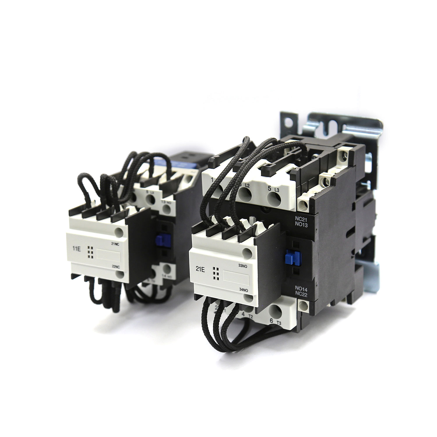
A CJ19 low-voltage power capacitor contactor is designed for capacitor switching applications. Selection should follow its applicable ratings and the bank design rather than treating it as an interchangeable general-purpose contactor. Switching capacitors involves inrush and repeated operations that deserve dedicated consideration. The same principle applies to fuses, breakers, discharge devices, and interlocks.
Where harmonic studies indicate a need, a detuned reactor may be part of the solution. Its purpose is not merely to add another component; it changes the combined circuit behavior to address resonance risk according to the designed tuning. The reactor and capacitor must be selected as a coordinated set. Do not retrofit a reactor ratio without reviewing the voltage, frequency, capacitor rating, and measured harmonic spectrum.
Selection Questions That Prevent Misapplication
Start by characterizing the load. Is reactive power fairly constant, or does it change with production cycles? Is the site supplied at low voltage or medium voltage? What power-factor requirement applies at the point of connection? What are the expected voltage variation, ambient conditions, and available fault level? These questions narrow the suitable types before a kvar value is chosen.
Next, examine power quality. A power analyzer should capture representative states, not only a quiet period. Nonlinear loads can raise harmonic current, and capacitor application can move a resonance point. The correct response may be a detuned bank, active harmonic filtering, a different placement, or a control strategy that avoids certain operating states. “Improve power factor” is not enough information to select safely.
Finally, consider ownership after commissioning. Can technicians isolate, discharge, inspect, and service the assembly safely? Are alarms visible or connected to the building-management or plant-monitoring system? Is there enough ventilation and clearance? Zhejiang Zhegui Electric Co., Ltd. markets these power-quality product categories under Giantele, but a suitable solution still depends on the buyer’s drawings, measurements, applicable EU-market requirements where relevant, and operating practice.
Limits and Maintenance Considerations
A capacitor bank does not correct every power-quality issue. It does not eliminate harmonics simply by being present, it does not replace a protection study, and it cannot compensate beyond its available stages. Its reactive output also changes with voltage, so performance at one voltage may not equal performance at another. For systems with significant fluctuation or distortion, a basic fixed bank can be the wrong tool.
Maintenance should include de-energized safety procedures, visual inspection, cleaning where the environment requires it, review of ventilation, inspection of terminal connections in accordance with approved torque practice, switching-device condition, controller alarms, and trend review of power factor and harmonic data. Re-evaluate the installation when major loads, transformers, generator operating patterns, or utility requirements change.
How to Estimate the Required Reactive-Power Change
Early sizing often starts with measured real power and the existing and desired power-factor conditions. A commonly used calculation is required kvar = kW × (tan arccos existing power factor − tan arccos target power factor). It is a planning tool, not a complete design. The measured kW must represent the operating condition being corrected, and the result should be tested against changing load, voltage, harmonics, switching steps, and the site’s actual commercial requirements.
For example, an engineer may calculate a compensation need at one production level and then find that the same bank would be excessive during a low-load shift. That is why automatic power factor correction uses multiple stages rather than one permanently connected value in many facilities. The calculation identifies the scale of the problem; controller step selection determines whether the installed system can follow it gracefully.
Capacitor Banks and Other Power-Quality Measures
Power factor correction is one part of a broader power-quality plan. A capacitor bank is not a substitute for correcting loose connections, overloaded conductors, voltage imbalance, poorly performing motors, or uncontrolled harmonic sources. In some cases, improving the process load or correcting an electrical defect first changes the required compensation size. In others, the bank is one coordinated element alongside filtering, monitoring, voltage regulation, and preventive maintenance.
This perspective helps procurement teams compare alternatives fairly. The right question is not “which cabinet has the largest kvar rating?” but “which controlled system addresses the measured operating condition with acceptable risk and maintainability?” Reliable input data and a documented decision basis are more valuable than a generic rule of thumb.
Read the Results at the Right Point
Measurements should be interpreted at the point that matters. A bank can improve the incoming power factor while feeder current downstream of its connection remains unchanged. A local bank can reduce feeder current while the utility meter sees only part of the improvement. Neither observation is necessarily a problem; it simply reflects the location of the reactive-power source. State the intended measurement point in the project brief and use the same point for acceptance testing.
Compare results at equivalent load levels whenever possible. A power factor measured after production drops cannot fairly demonstrate the effect of the installed equipment. Record kW, kvar, kVA, current, voltage, and the number of active stages so that later reviewers can understand what the system was doing. This basic discipline turns a claimed advantage into an auditable operating result.
Conclusion
A capacitor bank works by providing reactive power close to inductive demand, which can improve power factor and reduce upstream current. Its value comes from fit: fixed systems suit stable loads, automatic stages suit change, detuned designs address defined harmonic risks, and dynamic technology supports demanding profiles. For Giantele customers, the most useful first step is a measured view of the electrical distribution system followed by an application-specific selection and commissioning plan.
FAQs
Does a capacitor bank reduce kWh consumption?
It primarily reduces reactive demand and can reduce losses in parts of the system. The effect on billed energy depends on the tariff, load, location, and actual system losses; it should be measured rather than assumed.
What is the difference between a fixed and automatic capacitor bank?
A fixed bank supplies one connected reactive value. An automatic bank uses a controller and switching stages so it can add or remove compensation as the load changes.
Why is a detuned reactor used with capacitors?
It is used in designs that need to manage resonance risk and harmonic conditions. Its parameters must be selected from a system assessment, not chosen independently from the capacitors.
Can a capacitor bank cause a leading power factor?
Yes. If too much capacitive reactive power remains connected when inductive load is low, the site can become leading. Appropriate stage sizes and controller settings help prevent this.
How often should a capacitor bank be inspected?
The interval should follow the manufacturer’s instructions, local procedures, environment, and criticality. A site with dust, heat, frequent switching, or changing loads may need closer attention than a clean, stable installation.