


A capacitor bank can reduce avoidable reactive-power demand, but only when its location, protection, sensing, and controller settings match the electrical system. This guide is for facility engineers, panel builders, and commissioning teams working on low-voltage power factor correction. It explains the decisions to make before installation, the checks that matter during wiring, and a disciplined way to program and test an automatic system. It is not a substitute for a site-specific design, utility rules, or work by qualified electrical personnel.
Key Takeaways
- Start with measured load and harmonic data; a nameplate capacity alone does not define a suitable capacitor bank installation.
- Locate the controller current transformer so it measures the load that the system is intended to correct, then verify phase relationship before enabling automatic switching.
- Program voltage, CT ratio, target power factor, step sizes, switching delay, and alarm limits from documented site data rather than factory assumptions.
- Commission by observing real load changes and recording results; do not judge success solely by a controller display at one moment.
Begin With an Electrical Survey, Not a Cabinet Location
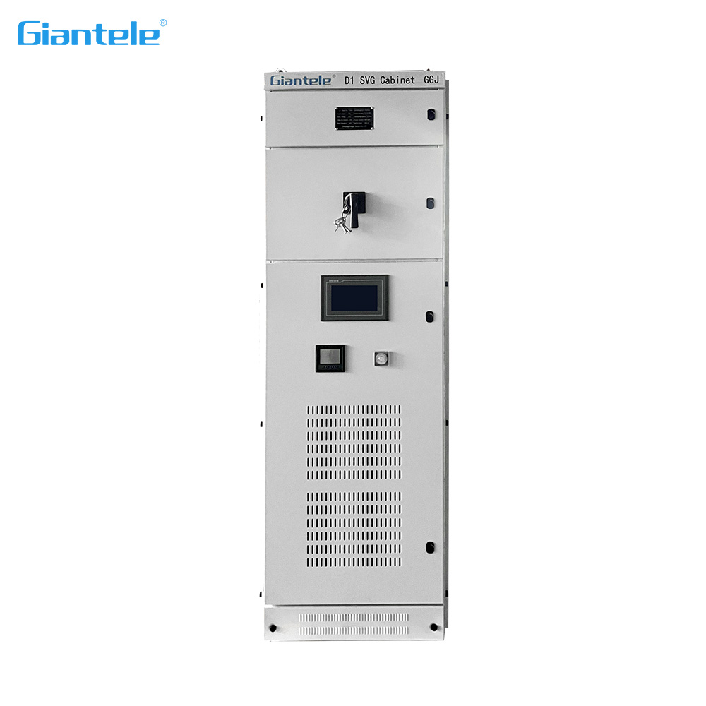
Installation begins with a power-quality and load review. Obtain interval demand data where it is available, then measure voltage, current, true power, power factor, and harmonic distortion across representative operating states. The useful question is not simply “how many kvar are needed?” It is whether the reactive demand is steady, staged, rapidly changing, or mixed with nonlinear loads. A stable motor load may suit contactor-switched stages, while abrupt cyclic loads can call for a faster response strategy such as the intelligent SVG panel offered by Giantele.
Map the single-line diagram before deciding where compensation belongs. Centralized correction at a main distribution board is convenient to maintain and can improve the facility billing point. Local correction near a large inductive load can reduce current in an upstream feeder. There is no universal placement rule: the selected point should reflect what the meter sees, how the loads operate, available fault duty, cable routing, ventilation, and safe access. A capacitor bank should be installed in an enclosure or electrical room suited to its environment, not placed wherever floor space happens to be open.
Harmonics deserve an early decision. Capacitors and inductive system impedance can form resonant conditions that increase stress instead of improving power quality. Where drives, rectifiers, welders, UPS equipment, or similar nonlinear loads are material, the design team should review harmonic measurements and system studies. For a useful background on sizing and power factor correction, see Giantele’s capacitor bank guide. A conventional bank may need detuning, filtering, or an active solution. Do not add stages to a troubled system until that question is resolved.
Installation Design: What Must Be Defined
A practical installation package identifies the incoming voltage and frequency, system grounding arrangement, prospective short-circuit current, conductor routing, protective-device coordination, and access restrictions. It also documents the rated steps and their switching device, discharge arrangements, controller I/O, CT type and ratio, and any interlocks. This turns field work into a checkable installation rather than a series of assumptions.
| Design item | Why it matters | Field confirmation |
|---|---|---|
| Supply and fault rating | Defines equipment suitability and protection coordination. | Compare nameplates and approved drawings with the actual switchboard. |
| Step arrangement | Affects how closely the system can follow reactive-load changes. | Confirm each stage, switching device, fuse or breaker, and discharge path. |
| CT location and polarity | Determines whether the controller calculates the correct load condition. | Trace primary conductors; check the CT label, ratio, orientation, and secondary terminals. |
| Harmonic strategy | Prevents inappropriate capacitor application on distorted networks. | Review measurement report and installed reactor or active-filter arrangement. |
| Environment | Heat, dust, moisture, and restricted airflow shorten component life. | Inspect clearances, cooling path, ingress risks, and maintenance access. |
Use the project drawings, local code, and the manufacturer’s instructions to define cable sizes, terminal torque, earthing, isolation, and overcurrent protection. Those values must not be copied casually from another site because available fault level, conductor installation method, and equipment ratings vary. Lockout/tagout, absence-of-voltage verification, stored-energy discharge, and appropriate PPE are essential work controls; capacitors can retain hazardous charge after isolation.
Fit and Wire the Capacitor Bank Methodically
Before energization, compare the delivered unit against the approved bill of materials. Check the enclosure, device labels, voltage rating, capacitor stages, controller, drawings, and loose components. Mount the cabinet on a suitable surface, preserve required clearances, and keep cable entries and ventilation openings from becoming paths for dust or water. Separate power conductors from low-level CT and communication wiring where the design requires it.
Connect the protective earth first and make the power connections only after the isolation procedure is verified. Follow the exact phase designations shown on the drawings. At this point, an experienced installer should also check that contactors or switching devices move freely, capacitor terminals are secured to the specified torque, and discharge devices are present. Giantele's active harmonic filter panel is a relevant companion where the load study calls for both reactive compensation and harmonic-management capability; it should still be installed and commissioned as its own coordinated system.
The CT circuit is the most common source of programming failures. The controller needs a current signal that represents the intended uncompensated load. Confirm which phase is monitored, whether one or three CTs are required, the CT primary-to-secondary ratio, polarity marking, and whether the CT is upstream of the compensation connection. Never open a CT secondary under load unless the procedure and equipment specifically make it safe. Label the circuit so a later maintenance change does not quietly reverse the original design.
Program the Controller From a Verified Data Sheet
A capacitor bank controller converts voltage and current information into switching decisions. It cannot correct a wiring or design error by itself. Create a commissioning sheet that records every value before changing menus: nominal line voltage, frequency, CT ratio, phase sequence, target power factor, connection mode, number of stages, stage kvar values, switching delay, reconnection delay, alarm thresholds, and communication settings. Record the default configuration too, so changes are traceable.
Set a target power factor that follows the facility’s engineering and commercial requirements. Chasing an unnecessarily leading condition can create a different operating problem. The target should work with the actual tariff, generator operating modes, transformer loading, and site rules. Configure the controller for the actual stage sequence rather than assuming identical steps. A bank with unequal stages is useful only when the controller recognizes their values and can choose a sensible combination.
Time delays are a control decision, not a cosmetic preference. If the delay is too short, the system may hunt by switching in and out during ordinary load variation. If it is too long, the facility may remain under-corrected through important demand periods. Capacitor discharge and switching-device requirements also limit how soon a disconnected stage can be reconnected. Use manufacturer guidance and observe the load cycle during commissioning before finalizing these parameters.
Commissioning Checklist and Acceptance Tests
Commissioning should proceed from de-energized checks to controlled energized observations. Start by reviewing documentation, conducting visual and mechanical checks, verifying insulation and continuity tests where the approved procedure calls for them, and confirming protective settings. Energize without automatically adding all stages. Verify measured voltage, current, frequency, phase sequence, and power factor against a trusted test instrument. If the controller readings are implausible, stop and resolve CT location, polarity, wiring, or programming before continuing.
Then test each stage deliberately. Observe the switching indication, current response, measured power factor, alarm behavior, and return-to-service timing. Where practical, vary the load in a controlled manner and confirm that the controller adds and removes stages in the expected order. Record before-and-after measurements at meaningful load points. Also confirm that the system does not become leading when major loads stop, and review temperature and ventilation after a sustained operating period.
Acceptance is stronger when the final handover includes the updated single-line diagram, terminal schedule, parameter record, protection settings, test results, maintenance instructions, and a clear note of the harmonic assumption used in the design. This information makes future troubleshooting far faster than a cabinet label alone.
Common Programming Problems and Their Likely Causes
A controller that never switches may be seeing the wrong CT ratio, insufficient reactive demand, a reversed phase relationship, an inhibited input, or alarm lockout. A controller that switches repeatedly may have an aggressive delay, step sizes that are too coarse for the load, unstable measurement, or a target that cannot be maintained under the site’s operating pattern. A displayed leading power factor after stages close may indicate excess compensation, incorrect phase association, or an error in the controller mode. Treat each symptom as evidence to investigate, not a reason to keep changing settings at random.
Maintenance teams should periodically inspect ventilation, capacitor condition indicators if provided, connections, switching-device wear, controller alarms, and the trend of power factor and harmonics. Any change in major loads—such as an added drive line, transformer change, or generator operating regime—can justify another review of the capacitor bank settings and harmonic suitability.
Use the Load Profile to Refine Stage Strategy
A useful post-commissioning review compares the stage pattern with the load profile. If the controller usually needs one small correction but occasionally requires several large changes, a bank with only equal, large stages may be less precise than the process requires. Conversely, many very small stages can add complexity and switching activity without a measurable gain. Review trend records for the number of operations, time spent outside the target range, and events at shift changes or equipment starts. These records help the engineering team decide whether the existing sequence is appropriate.
The review should include conditions that are easy to overlook: standby generators, seasonal HVAC operation, lightly loaded weekends, and plant expansions. A parameter set that works during normal production may not be correct when the supply arrangement changes. Good programming therefore has two outputs: settings that work now, and a documented rationale that allows a competent person to revisit them when the system changes.
Conclusion
Reliable capacitor bank installation and programming come from treating the unit as part of the distribution system rather than a stand-alone energy-saving device. Measure the load, establish a harmonic strategy, document the CT scheme, install to approved drawings, and prove the controller’s decisions under real operating conditions. Zhejiang Zhegui Electric Co., Ltd. supplies power-factor-correction equipment under the Giantele brand, but the final selection and settings should always be validated against the specific electrical network. A disciplined survey and commissioning record protect both equipment performance and the people who maintain it.
FAQs
Where should a current transformer be placed for a capacitor bank controller?
It should be placed so it measures the load that the controller is intended to correct, using the approved single-line diagram and controller instructions. Confirm polarity and phase association during commissioning; an incorrect location or orientation can make the controller respond in the wrong direction.
Can a capacitor bank be installed on a system with variable-frequency drives?
Possibly, but the application requires a harmonic review. Drives can introduce distortion and resonance risks. The right solution may include detuned reactors, filtering, or active compensation rather than an unreviewed conventional bank.
What controller settings should be recorded at handover?
Record nominal voltage and frequency, CT ratio, target power factor, stage sizes and sequence, switching and reconnection delays, alarm limits, phase configuration, communication parameters, and the date and person responsible for the setting change.
Why does a capacitor bank switch on and off repeatedly?
Frequent switching can result from rapidly changing load, short time delays, oversized steps, an unsuitable target, or unstable or incorrectly wired CT inputs. Review measured data and the configuration before altering hardware.
Is commissioning complete when the controller shows a good power factor?
No. The reading should be checked against an independent instrument and observed through expected load changes. Protection, phase relationship, stage operation, alarms, temperatures, and the risk of leading power factor also require confirmation.