

Introduction
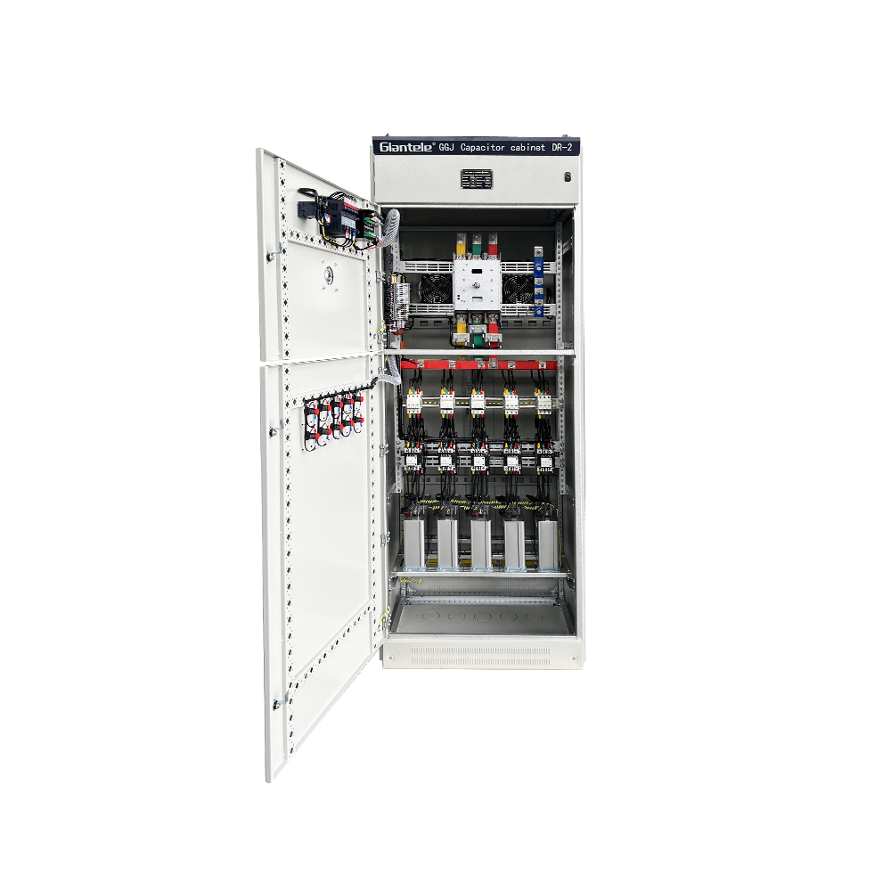
A capacitor bank is one of the most cost-effective investments a factory or substation can make. When your electrical system draws more reactive power than it needs, your utility charges you a penalty — and your cables, transformers, and switchgear all run hotter than they should. Cap banks fix this by supplying reactive power locally, so your grid connection only carries useful active power.
This guide explains how capacitor banks work, how to size them correctly, and when to choose a fixed bank, an automatic power factor controller (APFC panel), or a Static Var Generator (SVG). Whether you manage a factory in Uganda, a water utility in Kenya, or a mining operation in Angola, this article gives you the technical and commercial facts you need to make the right decision.

What Is a Capacitor Bank?
A capacitor bank is a group of power capacitors connected in parallel and housed in a single enclosure. Each individual power capacitor stores electrical energy in an electrostatic field. When the system voltage drops due to inductive load demand, the capacitor discharges its stored reactive power back into the network — instantly and silently.
The result is a higher power factor. Most utilities in Africa target a minimum power factor of 0.85 to 0.90. Below that threshold, they apply a reactive power surcharge to your monthly bill. A properly sized capacitor bank brings your power factor above the penalty threshold — and in most cases above 0.95.
Cap banks are not a new technology. But modern designs — with self-healing metallized polypropylene film dielectrics, microprocessor-based controllers, and detuned reactors — are far more reliable and efficient than the oil-filled paper capacitors of the past.
How a Capacitor Bank Works
Inductive loads — motors, transformers, fluorescent ballasts — draw two types of current. Active current does real work: it drives the motor shaft, heats the element, or lights the lamp. Reactive current creates the magnetic field that makes the motor run, but it does no useful work. It flows back and forth between the load and the generator, loading the cables and transformers with current that produces no kilowatt-hours on your meter.
A capacitor bank supplies this reactive current locally. The motor still gets the reactive current it needs, but it comes from the capacitor sitting next to it rather than from the utility grid 10 kilometres away. Your meter sees only active current. Your power factor rises. Your cable losses fall.
The ratio of active power (kW) to apparent power (kVA) is your power factor. Mathematically:
Power Factor = kW ÷ kVA = cos θ
A power factor of 0.70 means 70% of the current you are paying to carry is doing real work. A power factor of 0.95 means 95% is productive. The difference is not trivial: raising power factor from 0.70 to 0.95 in a 500 kVA substation reduces reactive current by roughly 60%.

Power Factor Correction Calculations: How to Size Your Capacitor Bank
Getting the kvar rating right is critical. An undersized bank leaves penalty charges on the table. An oversized bank creates leading power factor — which can cause voltage rise and damage sensitive equipment.
The standard power factor correction calculation uses this formula:
Q (kvar) = P (kW) × (tan θ₁ − tan θ₂)
Where:
P = your active load in kilowatts
θ₁ = the angle corresponding to your current (poor) power factor
θ₂ = the angle corresponding to your target power factor
Example: A flour mill in Kampala draws 350 kW at a power factor of 0.72. The utility penalty threshold is 0.90.
Parameter | Value |
|---|---|
Active load (P) | 350 kW |
Current power factor | 0.72 (cos θ₁) |
tan θ₁ | 0.964 |
Target power factor | 0.92 (cos θ₂) |
tan θ₂ | 0.426 |
Required kvar = 350 × (0.964 − 0.426) | 188 kvar |
So the mill needs a 200 kvar capacitor bank (rounding up to the nearest standard size). Most manufacturers offer standard sizes in steps of 25, 50, 75, 100, 150, 200, 250, 300, and 400 kvar. The U.S. Department of Energy's guide on reducing power factor cost provides additional worked examples and payback calculation templates applicable to any industrial site.
For sites with variable loads — shift-based production, seasonal fluctuations, or mixed motor and lighting loads — a fixed bank is rarely enough. You need an automatic power factor controller that switches individual capacitor steps in and out as the load changes.
Types of Capacitor Banks
Fixed Capacitor Bank
A fixed bank connects a set kvar value permanently to the busbar. It suits sites where the reactive power demand is nearly constant — such as a pump station running 24 hours a day at full load. Fixed banks are simple, low-cost, and require minimal maintenance.
Limitation: They cannot respond to load changes. If production stops and the load drops, a fixed bank can push the power factor into the leading zone — causing voltage rise and potential equipment damage.
Automatic Capacitor Bank (APFC Panel)
An APFC panel uses an automatic power factor controller — a microprocessor relay — to monitor the busbar power factor in real time. When the power factor falls below the target, the controller switches in one or more capacitor steps. When the load drops, it switches steps out. The result is a stable power factor between 0.92 and 0.98 across all load conditions.
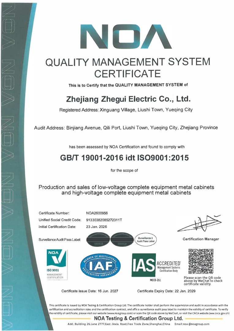
A typical Giantele APFC panel includes:
Microprocessor-based automatic power factor controller relay (JKL5 or equivalent)
Capacitor steps from 25 kvar to 200 kvar per step
CJ19 capacitor contactors for surge-free switching
Detuned reactors (typically 7% or 14%) to prevent harmonic resonance
Overcurrent and overvoltage protection relays
Steel enclosure to IEC 61439, IP42 to IP54
Ratings range from 50 kvar to 2,000 kvar, at 380V to 690V, 50 Hz or 60 Hz. This covers the full range from a small commercial building to a large industrial substation.
Static Var Generator (SVG)
An SVG panel replaces capacitor banks entirely with a power electronics inverter. It generates or absorbs reactive power steplessly and responds in under 10 milliseconds — compared to the 20–200 milliseconds of a contactorswitched capacitor bank. SVG panels are preferred on sites with rapidly fluctuating loads: arc furnaces, welding machines, large motor starts, or wind farms.
The SVG also suppresses voltage flicker and can absorb reactive power as well as generate it — something a capacitor bank cannot do.
Key Components Inside a Capacitor Bank
Understanding what is inside the panel helps you specify, commission, and maintain it correctly.
Component | Function |
|---|---|
Power capacitor | Stores and supplies reactive power; self-healing metallized film |
Switches each kvar step; built-in inrush suppression resistor | |
Detuned reactor (CKSG) | Blocks harmonic resonance; typical detuning 5.67%, 7%, or 14% |
Automatic power factor controller | Measures power factor; sends switching commands to contactors |
Overcurrent relay | Protects capacitors from sustained overload |
Busbar and enclosure | Distributes current; provides IP-rated environmental protection |
The detuned reactor deserves particular attention. In any network with variable frequency drives or other non-linear loads, the capacitor bank can resonate with the system inductance at harmonic frequencies — typically the 5th or 7th harmonic. This resonance amplifies harmonic voltages and currents, damaging both the capacitors and nearby equipment. A detuned reactor connected in series with each capacitor step raises the resonant frequency above the dominant harmonic, eliminating the risk.
For sites with severe harmonic distortion — THD above 10% — consider combining the capacitor bank with an active harmonic filter rather than relying on detuned reactors alone.
Power Factor Correction in African Industrial Sites
Uganda, Kenya, and Angola all have electricity tariff structures that penalise low power factor. Both the Uganda Electricity Regulatory Authority and the Energy and Petroleum Regulatory Authority of Kenya require industrial consumers to maintain a minimum power factor — typically 0.85 — or pay a reactive energy surcharge. The IEEE 1036-2020 guide for the application of shunt power capacitors sets out how to calculate the correct bank size and avoid over-compensation that could itself attract penalties.
Beyond tariff compliance, the infrastructure reality in many African cities makes good power factor management even more important:
Transformer capacity is limited. Many industrial estates share a substation with inadequate kVA capacity. Improving power factor releases apparent power capacity — effectively giving you more kW from the same transformer.
Cable infrastructure is aging. Lower current (because reactive current is now supplied locally) means less voltage drop over long LV cable runs — a critical issue on sites where the transformer is 200 metres from the production building.
Generator sets are expensive to run. On sites with diesel backup, a capacitor bank reduces the apparent power demand on the generator, allowing a smaller genset to carry the same productive load.
Sites with variable frequency drives, welding machines, or rectifiers also need to consider harmonic resonance. IEC 61921:2017, the international standard for low-voltage power factor correction banks, requires that manufacturers declare the harmonic withstand capability of their capacitor banks. The AfDB Electricity Regulatory Index 2024 tracks regulatory quality and grid infrastructure maturity across 54 African countries — Uganda, Kenya, and Angola are all included — and consistently identifies reactive power management as a key gap in distribution system efficiency across the continent.
How to Choose Between a Capacitor Bank and an SVG
This is the most common question buyers ask. The answer depends on three factors: load variability, harmonic content, and budget.
Criterion | Capacitor Bank (APFC) | Static Var Generator (SVG) |
|---|---|---|
Load variability | Moderate (step-switched) | High (stepless, <10 ms) |
Harmonic filtering | Partial (detuned reactor) | Full (with AHF option) |
Response speed | 20–200 ms | <10 ms |
Voltage flicker control | No | Yes |
Capital cost | Lower | Higher |
Maintenance | Capacitor replacement every 8–15 years | IGBT module inspection annually |
Best application | Factories, pumping stations, commercial buildings | Arc furnaces, welding, mines, wind farms |
For most factories, food processors, cold storage facilities, and commercial buildings in Africa, an APFC panel is the right choice. It delivers excellent power factor correction at a capital cost 40–60% lower than an equivalent SVG. The EPRA Kenya Electricity Grid Code explicitly mandates that generators and large consumers maintain a power factor between 0.85 lagging and 0.95 leading — a range that a correctly sized APFC panel achieves automatically, with no manual intervention. For heavy industry with fluctuating loads — steel mills, cement plants, large mining compressors — an SVG pays back the premium cost through superior voltage stability and reduced equipment downtime.
Frequently Asked Questions
What is the difference between a capacitor bank and a power factor capacitor? A power factor capacitor is a single capacitor unit — typically 5 to 60 kvar. A capacitor bank is a group of these capacitors assembled in a panel, often with automatic switching, protection relays, and detuned reactors included.
Can I install a capacitor bank at the motor terminal instead of the main switchboard? Yes. Terminal power factor correction places the capacitor directly at the motor, so the reactive current does not flow through any of the upstream cabling. This gives the maximum reduction in cable losses. But it requires one capacitor per motor — which increases the number of units to maintain. Most sites use a combination: individual capacitors at large motors and a central APFC panel at the main switchboard.
What happens if my capacitor bank is oversized? An oversized bank pushes the power factor into the leading zone (above 1.0 on the scale). This causes the voltage to rise above nominal — which can stress sensitive equipment and trigger protection relays. It can also cause the utility meter to record a leading reactive energy import, which some tariffs also penalise. Always size the bank to reach a target power factor between 0.92 and 0.97, not 1.0.
How often do power capacitors need to be replaced? Self-healing metallized film capacitors built to IEC 60831-1:2014 have a design life of 100,000 hours under rated conditions — roughly 11 years of continuous operation. In practice, capacitor life is shortened by overvoltage, high ambient temperature, and harmonic overload. Inspect capacitors annually for bulging, leakage, or capacitance drop. Replace any unit showing more than 5% capacitance loss or visible physical damage.
Does a capacitor bank affect harmonics? A plain capacitor bank can amplify harmonic currents through resonance. A capacitor bank with detuned reactors avoids resonance. An active harmonic filter eliminates harmonics directly. If your site has significant harmonic sources — VFDs, UPS systems, arc furnaces — always use detuned reactors as a minimum, and consider an active harmonic filter if the total harmonic distortion (THD) exceeds 8%.
Conclusion
A capacitor bank — whether a fixed bank, an automatic power factor controller panel, or a modern SVG — is not just a compliance tool. It is a practical way to reduce electricity bills, extend the life of cables and transformers, release transformer capacity, and improve voltage stability across your site.
The right solution depends on your load profile, harmonic environment, and budget. For most industrial and commercial sites in Uganda, Kenya, and Angola, a properly sized APFC panel with detuned reactors delivers the best return on investment. For sites with volatile loads or severe harmonic distortion, an SVG or a combined APFC-plus-active-harmonic-filter system is the engineering-sound choice.
Giantele manufactures the full range — from individual power factor capacitors and CJ19 capacitor contactors to complete APFC panels and SVG systems — at our factory in Zhejiang, China. Every panel ships with a single-line diagram, test certificates, and commissioning support. Contact our technical team at giant-electric.com/contactus.html to get a sizing calculation and quotation for your site.
-
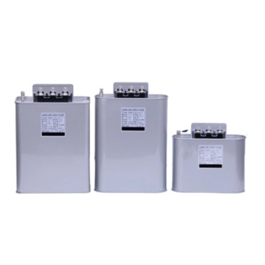 In many industrial and utility projects we support, the conversation about reactive power starts simple—“We need to improve power factor”—and then quickly becomes confusing when different teams use the same words to mean different things. Some people say “capacitor” when they mean an entire cabinet with steps, contactors, fuses, and a controller. Others say “capacitor bank” when they actually need only a single power capacitor installed near a motor control center, a transformer secondary, or an MV feeder.
 -
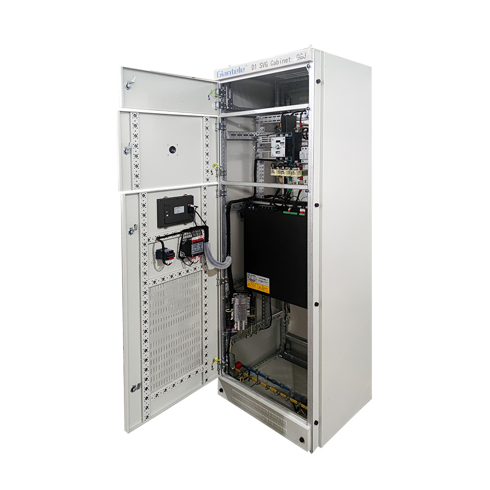 This document presents a structured methodology for calculating reactive compensation capacity (kvar) required for power factor correction in electrical distribution systems. Three principal techniques are detailed:1.Precision Calculation Method (Recommended); 2.Energy-Meter Derived Averaging Method; 3.Transformer-Based Empirical Estimation.
 -
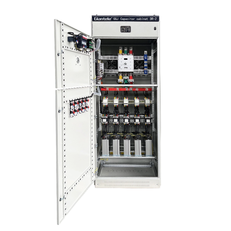 I. Definition: The Reactive Power SolutionA capacitor bank (often called a Reactive Power Compensation Unit) is a crucial device for optimizing power supplies and overall electrical system efficiency. Manufactured to the stringent International Electrotechnical Commission standard IEC 62271, it cons
 - This document presents a structured methodology for calculating reactive compensation capacity (kvar) required for power factor correction in electrical distribution systems. Three principal techniques are detailed:1.Precision Calculation Method (Recommended); 2.Energy-Meter Derived Averaging Method; 3.Transformer-Based Empirical Estimation.
