


A VFD control panel is not simply a variable frequency drive mounted in a steel enclosure. It is a coordinated motor-control system designed around the motor, driven load, incoming power supply, installation environment, operating method, and maintenance requirements.
When these factors are considered together, a VFD panel can provide stable speed control for pumps, fans, conveyors, mixers, compressors, and other motor-driven equipment. When they are not, the result may be overheating, nuisance trips, unstable signals, difficult commissioning, or limited access for future service.
At Giant Electric, each VFD panel configuration should begin with the application rather than the cabinet size or the drive power rating alone. Motor data, load behavior, available fault level, cable routing, control logic, and environmental conditions all influence the final design.
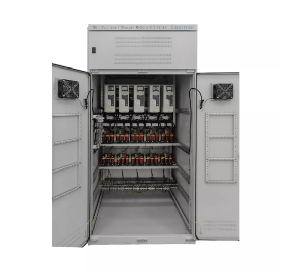
Start With a Clear VFD Panel Design Brief
Before selecting a VFD, breaker, enclosure, or cooling system, collect the information that defines the application.
Design Input | Questions to Confirm | Why It Matters |
|---|---|---|
Incoming power | What are the supply voltage, frequency, phase, grounding arrangement, and available fault level? | Determines VFD input rating, protective-device selection, and panel short-circuit requirements. |
Motor data | What are the motor voltage, full-load current, power, speed, insulation class, and service factor? | Supports accurate VFD and cable selection. |
Load type | Is the load a pump, fan, conveyor, mixer, compressor, extruder, or another machine? | Determines torque demand, acceleration behavior, and overload requirements. |
Operating range | What are the required minimum and maximum speeds? How often does the motor start and stop? | Affects control settings, motor cooling, and system performance. |
Installation environment | Will the panel be installed indoors, outdoors, in a dusty area, a humid room, or a corrosive location? | Determines enclosure rating, cooling method, and component protection. |
Control method | Is operation local, remote, automatic, sensor-based, PLC-controlled, or networked? | Defines the required push buttons, I/O, terminals, communication hardware, and control logic. |
Process continuity | Can the process stop during maintenance? Is bypass or redundancy required? | Influences panel architecture and operational risk planning. |
Motor nameplate data is especially important. Do not select a drive only by motor horsepower or kilowatt rating. The motor full-load current, overload demand, speed range, duty cycle, and load profile must also be reviewed.
For example, a centrifugal pump or fan normally has a variable-torque load. A conveyor, mixer, positive-displacement pump, or loaded production machine may need more stable torque across its operating range. Large fans, loaded conveyors, and other high-inertia equipment may also need longer acceleration and deceleration times to avoid overcurrent or overvoltage faults.
These same inputs are useful when preparing an enquiry. A complete VFD panel specification helps avoid selecting a panel that is either oversized for the process or unable to handle actual operating conditions.

Follow a Practical VFD Panel Design Workflow
A reliable VFD panel design usually follows a clear sequence:
Confirm the incoming power supply and available fault conditions.
Review the motor nameplate and driven-load characteristics.
Select the VFD based on current, overload duty, control requirements, and operating range.
Design the incoming protection, isolation, and power distribution arrangement.
Evaluate output-side protection, motor cable length, reactors, filters, and grounding.
Size the enclosure, thermal-management system, terminals, wireways, and service clearances.
Develop the control, safety, alarm, communication, and interlock logic.
Complete factory testing and provide drawings, terminal schedules, parameter records, and operation documents.
This sequence prevents a common mistake: choosing a drive first and trying to fit all remaining components around it later. The VFD is the core device, but the complete panel must operate as one system.

Select the VFD for the Motor and Load
The VFD should match the motor voltage, phase, rated current, frequency, and required overload capacity. However, those basic values are only the starting point.
The load type should guide the drive selection. Pumps and fans often benefit from variable-torque control, where motor torque changes with speed. Conveyors, mixers, crushers, and positive-displacement pumps may need higher starting torque or more stable low-speed torque. A heavy conveyor or large fan wheel can also create high inertia during acceleration and deceleration.
When reviewing a VFD, consider the following factors:
Continuous output current required by the motor
Overload rating needed during startup or temporary load changes
Required speed range and low-speed operating time
Control mode, such as V/F control, sensorless vector control, or closed-loop control
Local, remote, or automatic operating requirements
Communication needs, such as Modbus, Profibus, Ethernet, or PLC integration
Braking requirements for high-inertia loads or rapid deceleration
Motor suitability for inverter operation
A motor operating continuously at low speed may receive less airflow from its shaft-mounted cooling fan. This is particularly important for constant-torque loads. Depending on the application, the motor may need an independently powered cooling fan, a larger motor, a defined minimum operating speed, or another thermal solution.
Design the Incoming Power and Protection Circuit
The incoming circuit must provide safe isolation and coordinated protection for the VFD panel. A typical arrangement may include a main disconnect switch or circuit breaker, upstream short-circuit protection, incoming terminals, and properly sized power conductors.
The exact protective-device configuration depends on the VFD manufacturer’s instructions, the available fault current, the local electrical code, the panel short-circuit rating, and the project’s electrical distribution system. Protective devices should not be selected from a generic rule alone.
The design review should confirm:
Input voltage and phase match the VFD rating
Main isolation can be operated safely during maintenance
Protective devices are compatible with the VFD manufacturer’s recommendations
The panel can withstand the expected short-circuit conditions
Incoming cables, lugs, and terminals are rated for the required current
Grounding and bonding connections are clearly planned
The installation allows safe access to the disconnecting device
For many industrial projects, an external door-coupled operating handle is useful because it allows isolation without opening the enclosure. The final selection should still match the enclosure rating and site environment.
Decide When Reactors, Filters, and Braking Components Are Needed
Not every VFD panel needs the same accessories. Line reactors, output reactors, filters, braking units, and harmonic-mitigation equipment should be selected according to the electrical system and application conditions.
Condition | Design Consideration |
Unstable incoming supply or power-quality concerns | Consider an input reactor, DC choke, or another measure recommended for the VFD and electrical system. |
Long motor cable runs | Review whether an output reactor, dv/dt filter, or sine-wave filter is needed to reduce stress on the motor and cable system. |
Sensitive nearby control signals | Improve cable separation, grounding, shielding, and EMC planning. |
High-inertia load or rapid stopping requirement | Assess whether a braking unit and braking resistor are needed. |
Harmonic limits or sensitive power system | Evaluate harmonic performance as part of the full electrical system, not as an isolated accessory decision. |
Outdoor or high-temperature environment | Consider the effect of heat on the VFD, filters, reactors, and enclosure cooling capacity. |
An input reactor can help reduce disturbances between the incoming supply and the drive. An output reactor or filter may be needed when long motor cables, motor-insulation concerns, switching frequency, or installation layout increase stress on the output circuit.
These components should be selected based on the actual project design. Adding accessories without a clear reason increases cost and space requirements, while omitting them when needed can reduce reliability.
Plan the Enclosure Layout and Thermal Design
A VFD panel should be easy to wire, inspect, maintain, and cool. A crowded enclosure often creates problems long before the panel reaches the customer’s site.
The layout should separate the main functional areas:
Incoming power and isolation section
VFD and power-device section
Output circuit and motor connection section
Control devices and PLC interface section
Terminal block and field-wiring section
Cooling, grounding, and cable-management section
The VFD must have sufficient clearance above, below, and around the unit for airflow. Wire ducts, terminal blocks, reactors, and other components should not block the manufacturer’s required ventilation paths.
Cooling design must consider more than the cabinet size. Review the maximum ambient temperature, total internal heat load, enclosure protection rating, solar exposure, altitude, dust level, filter maintenance, and nearby heat sources. A tightly sealed enclosure can provide better protection against dust or water, but it may also reduce natural heat dissipation.
Depending on the application, thermal management may include natural ventilation, filtered fans, roof-mounted fans, heat exchangers, air conditioning, thermostatic control, or internal heaters to reduce condensation risk.
The enclosure should also provide enough room for cable bending radius, field terminations, wireway access, door-mounted devices, and future service work. A panel that is difficult to maintain can create unnecessary downtime over its operating life.
For projects that require a configurable enclosure, integrated drive section, protection devices, and remote-control options, Giant Electric can provide a custom VFD panel arrangement based on the motor and site requirements.
Separate Power Wiring From Control and Signal Wiring
VFD output cables generate high-frequency electrical noise. If power, motor, analog, communication, and low-voltage control wiring are routed together without planning, the panel may experience unstable signals, communication faults, inaccurate sensor readings, or nuisance alarms.
Good wiring practice includes:
Separating incoming power, VFD output, control, analog, and communication wiring
Using separate wireways or physical spacing where appropriate
Keeping sensitive signal cables away from motor output cables
Using shielded cable where required by the installation and equipment instructions
Terminating cable shields correctly
Providing clear wire labels and terminal identification
Using a properly designed grounding and bonding arrangement
Matching all field terminals to the approved drawings and terminal schedule
A clean wiring layout is not only an appearance issue. It improves commissioning efficiency, makes fault tracing easier, and lowers the risk of incorrect field connections.
Clear terminal identification and a logical cabinet layout also save time when technicians trace a fault or reconnect field wiring. A well-organized VFD panel layout, wiring, and fault-checking process makes these routine tasks more efficient during commissioning and maintenance.
Design the Control and Safety Logic
A VFD panel may receive commands from local push buttons, selector switches, pressure sensors, flow sensors, PLCs, building-management systems, or remote communication networks. The design must define which command source has priority and what should happen if a signal, sensor, or communication connection fails.
Common control functions include:
Start, stop, reset, and emergency-stop functions
Hand-Off-Auto selector switch
Local and remote operating modes
Run, stop, fault, and power indication lights
Speed reference from keypad, potentiometer, analog signal, or communication network
Pressure, flow, temperature, or level feedback
Interlocks from upstream or downstream equipment
Alarm outputs for remote monitoring
Communication with PLC, SCADA, or building-management systems
A Hand-Off-Auto switch is often useful for pumps, fans, and industrial machinery. In Hand mode, the operator can run the equipment locally. In Off mode, the motor remains stopped. In Auto mode, the panel can accept commands from a PLC, sensor, or external control system.
The control logic should be tested before delivery. It is important to verify not only whether the motor runs, but also whether the panel responds correctly to stop commands, faults, interlocks, loss of feedback, and mode changes.
Example: Design Brief for an Outdoor Pump VFD Panel
Consider an outdoor pump station with a three-phase motor, pressure-based automatic control, local HOA operation, a remote PLC connection, and a dusty or humid environment.
The panel design would need to review:
Motor full-load current and pump load profile
Incoming voltage, fault level, and upstream protection
Required pressure-transducer signal and control range
Local HOA switch, start/stop controls, and fault indicators
Communication interface for PLC or remote monitoring
Enclosure rating for dust, moisture, temperature, and sunlight
Cooling method suitable for the expected ambient conditions
Cable routing between the drive, motor, sensor, and PLC
Grounding, shielding, and noise control for the analog pressure signal
Pump dry-run, low-pressure, high-pressure, or other process interlocks
This approach is more reliable than using the same standard panel configuration for every project. The application determines the design.
Complete Factory Acceptance Testing Before Delivery
Factory acceptance testing should verify the completed panel against the approved drawings and project requirements.
Check Item | Verification Focus |
Component installation | Confirm the VFD, breakers, terminals, reactors, cooling parts, and control devices match the approved design. |
Wiring inspection | Check wire routing, terminal tightening, labels, cable separation, grounding, and bonding. |
Power-circuit check | Verify the incoming, drive, output, and motor connection arrangement. |
Control-logic test | Test local, off, auto, start, stop, reset, run indication, fault indication, and interlocks. |
I/O and communication test | Confirm analog signals, digital inputs, relay outputs, PLC points, and communication functions. |
VFD parameter review | Check motor voltage, current, frequency, acceleration, deceleration, control mode, and protection settings. |
Cooling-system test | Confirm fans, filters, thermostats, heaters, or air-conditioning devices operate as intended. |
Documentation review | Prepare drawings, BOM, terminal schedule, parameter backup, test records, and operation guidance. |
The final documents should match the actual panel. Clear drawings, wire labels, terminal schedules, and VFD parameter records help installers, commissioning engineers, and maintenance teams work efficiently after delivery.
Conclusion
A dependable VFD control panel begins with a clear understanding of the motor, load, power supply, environment, and control requirements. Drive selection, protection, cooling, wiring, EMC planning, and testing should be treated as connected design decisions rather than separate tasks.
The best VFD panel for a project is not simply the one with the largest drive or the most accessories. It is the one that matches the application, supports safe installation and maintenance, and provides stable motor control throughout its operating life.
Giant Electric designs low-voltage power-distribution and motor-control solutions for industrial projects where electrical compatibility, maintainability, and site conditions must be considered together. Teams planning a broader motor-control system can also compare the role of a VFD panel with an industrial VFD control panel in plant applications.
FAQs about VFD Panel Design
What is a VFD control panel?
A VFD control panel is an enclosure that integrates a variable frequency drive with protection devices, control components, cooling equipment, wiring, terminals, and indicators. It controls motor speed while supporting safer operation, monitoring, and maintenance.
How do you size a VFD control panel?
Start with the motor full-load current, voltage, load type, overload demand, speed range, cable length, ambient temperature, control method, and available installation space. The enclosure and cooling system must also accommodate the heat generated by the VFD and other components.
When does a VFD panel need a line reactor or output reactor?
A line reactor may be considered when the incoming power system has disturbances or when additional input protection is recommended. An output reactor or filter may be needed for long motor cable runs, motor-insulation protection, or output-circuit conditions that increase electrical stress. Final selection should follow the VFD manufacturer’s guidance and project requirements.
Why does VFD panel cooling matter?
VFDs and related components generate heat during operation. If the enclosure cannot remove this heat, the drive may derate, trip, or experience reduced service life. Cooling design should consider ambient temperature, enclosure rating, internal heat load, dust, and ventilation conditions.
Can a VFD panel include a bypass?
Yes. A bypass arrangement can be considered when a process needs the motor to continue operating if the VFD is unavailable. Whether a bypass is appropriate depends on the motor, process, safety requirements, operating mode, and control architecture.
What is the difference between a VFD panel and an MCC?
A VFD panel is usually designed around one or more variable frequency drives for speed-controlled motors. A motor control center, or MCC, is a larger assembly that may contain multiple motor starters, VFD sections, feeders, protection devices, and control compartments for several motors.
What information should be provided for a custom VFD panel quotation?
Provide the motor nameplate details, incoming voltage and frequency, load type, required speed range, installation environment, enclosure requirements, local or remote control method, communication protocol, cable length, and any required sensors, alarms, bypass functions, or testing standards.