


Introduction
Selecting a VFD Control Panel requires more than matching a drive to the motor’s kilowatt or horsepower rating. The motor, mechanical load, power supply, enclosure, cooling system, cable length, control logic, and operating environment must work as one coordinated system.
An incorrectly specified VFD Control Panel may experience repeated trips, excessive heat, unstable speed control, electromagnetic interference, or premature component failure. This guide explains how the panel controls an industrial motor, which design factors affect reliability, how EU requirements apply, and what technicians should inspect during commissioning, maintenance, and troubleshooting.
How a VFD Control Panel Controls Motor Speed
A variable frequency drive regulates an AC motor by controlling the frequency and voltage of the electrical output. The drive first converts incoming AC power into DC power. An inverter stage then creates a controlled AC output with the frequency and voltage required for the selected motor speed.
Motor speed is closely related to output frequency. By increasing or decreasing that frequency, a VFD Control Panel can adjust the speed of pumps, fans, conveyors, mixers, compressors, and other motor-driven equipment without relying entirely on mechanical throttling or fixed-speed operation.
The panel is more than the drive itself. A complete VFD Control Panel normally integrates several functional areas:
Incoming power isolation and protection
Variable frequency drive equipment
Motor and circuit protection
Start, stop, reset, and speed controls
Status indicators and alarm signals
Cooling and ventilation components
Control terminals and communication interfaces
Organized power, motor, and signal wiring
The exact component arrangement depends on the application. A simple pump may require local start and stop commands with a pressure sensor, while a conveyor system may need a programmable controller, emergency interlocks, multiple permissive signals, and coordinated acceleration.
Controlled acceleration is one of the principal operational benefits. Direct starting can create high starting current and sudden mechanical stress. A VFD Control Panel gradually increases motor frequency and voltage, allowing the motor and connected equipment to accelerate more smoothly.
Controlled speed can also improve process regulation. A pump can respond to pressure or flow demand, and a ventilation fan can respond to temperature or air-quality signals. However, energy savings are not automatic in every application. The actual result depends on the load profile, operating hours, required speed range, and process conditions.
How to Select and Size a VFD Control Panel
Drive selection should begin with the motor nameplate, but nameplate power is only the starting point. Engineers should also consider rated voltage, full-load current, frequency, motor speed, insulation condition, operating duty, service factor, and the motor’s suitability for inverter operation.
The current rating is particularly important. Two motors with the same nominal power can have different full-load currents. A VFD Control Panel should provide sufficient continuous output current for the motor and enough overload capacity for acceleration, temporary process demand, and changing mechanical conditions.
Identify the Load Torque Profile
The driven load determines how much torque the motor must produce at different speeds. Centrifugal pumps and fans usually have variable-torque characteristics. Conveyors, positive-displacement pumps, mixers, extruders, and loaded production machinery often require relatively constant torque.
High-inertia equipment presents another challenge. Large fans, centrifuges, loaded conveyors, and similar machines may require longer acceleration and deceleration periods. If the acceleration time is too short, the VFD Control Panel may trip on overcurrent. If deceleration is too aggressive, regenerative energy may raise the DC bus voltage and cause an overvoltage trip.
The selection process should answer the following questions:
Selection Factor | Questions to Check | Design Effect |
|---|---|---|
Power supply | What are the voltage, frequency, phase, and available fault level? | Determines input rating and protective-device selection |
Motor | What are the full-load current, rated speed, and insulation conditions? | Determines drive capacity and output requirements |
Load | Is the load variable torque, constant torque, or high inertia? | Affects overload rating, control mode, and ramp settings |
Speed range | How slowly and how quickly must the motor operate? | Affects motor cooling and control performance |
Environment | Is the location hot, dusty, humid, corrosive, or exposed to water? | Determines enclosure and thermal-management requirements |
Control method | Will control be local, remote, sensor-based, or networked? | Determines switches, I/O, communication, and logic |
Process continuity | Can the machine stop while the drive is serviced? | Determines whether bypass or redundancy should be considered |
Motor cooling must also be evaluated. A motor with a shaft-mounted cooling fan receives less airflow when operating continuously at low speed. Constant-torque applications may therefore require an independently powered fan, a larger motor, or a defined minimum continuous speed.
Motor cable length can influence the output circuit. Long cables may increase electrical stress on the motor insulation and create additional charging current. Cable construction, grounding, switching frequency, motor design, and installation layout should be evaluated before deciding whether an output reactor or filter is needed.
VFD Control Panel Design Factors That Affect Reliability
Heat is one of the most common causes of reduced drive and electronic component life. A VFD Control Panel produces internal heat through the drive, power devices, transformers, contactors, reactors, and other components. The enclosure must remove that heat under the maximum expected operating conditions.
Thermal design should consider ambient temperature, altitude, dust loading, solar exposure, nearby heat sources, enclosure size, component spacing, and filter condition. A highly sealed cabinet may provide better environmental protection, but it also restricts natural airflow.
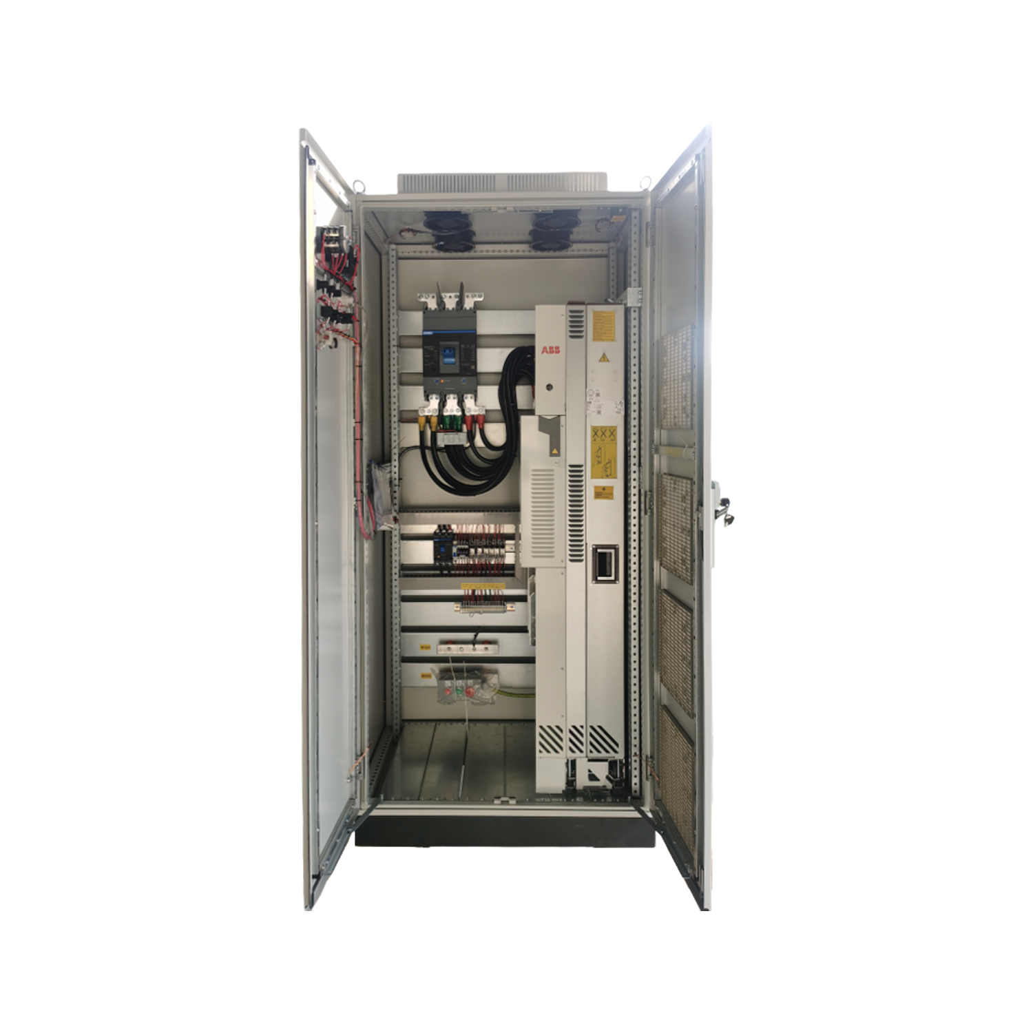
The Industrial VFD Panel includes an IP54 enclosure, thermal-management features, modular component access, built-in reactors, and RS485 or Ethernet communication options. These characteristics should still be checked against the required voltage, current, load type, installation environment, and control architecture.
Components must be installed with sufficient clearance for ventilation and maintenance. Drives should not be crowded against cabinet walls or placed where heat from lower components rises directly into sensitive electronics. Cooling fans and filters should remain accessible without requiring extensive panel disassembly.
Power and Control Wiring
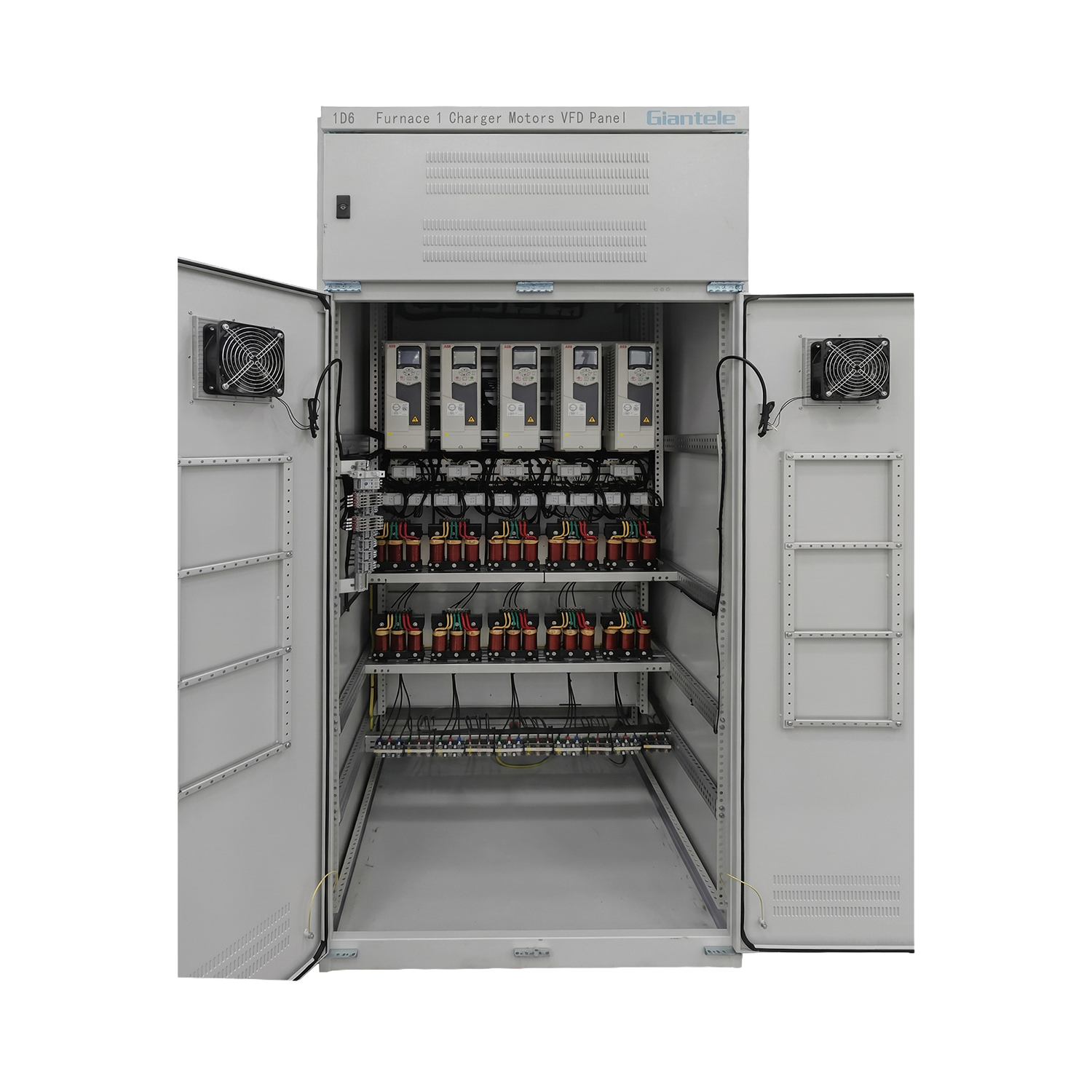
Power conductors, drive output cables, analog signals, communication wiring, and low-voltage control circuits should not be routed without separation. Motor cables generate high-frequency electrical noise that can interfere with sensors, communication networks, and low-level analog signals.
Shielding and grounding should provide a controlled path for interference while supporting electrical safety. Poor bonding, long grounding paths, and incorrectly terminated cable shields can contribute to unstable feedback values, communication faults, or unexplained control behavior.
The upstream feeder must be compatible with the VFD Control Panel input voltage, current, and short-circuit withstand requirements. A Low Voltage Distribution Board can provide the incoming feeder, protective devices, and distribution arrangement needed to supply the motor-control system. The referenced product is designed for low-voltage power distribution and includes overload, short-circuit, and leakage-protection options.
Where several motors are controlled from one centralized assembly, a Motor Control Center can integrate multiple motor feeders, starters, protective devices, and variable-frequency sections. The referenced MCC supports variable-frequency, soft-starter, and star-delta starting configurations, allowing the final arrangement to reflect different motor duties within the same facility.
Harmonics and Electromagnetic Interference
Variable frequency drives are nonlinear loads. Their input current can contain harmonic components that affect transformers, conductors, generators, capacitors, and other equipment connected to the same network.
Harmonic mitigation should be based on the electrical system rather than selected as an isolated accessory. Possible measures include line reactors, DC chokes, filters, suitable transformer capacity, and coordinated power-factor-correction equipment.
Electromagnetic interference must be addressed at both the panel and installation levels. Enclosure construction, cable routing, grounding, shield termination, filter selection, and separation between power and control wiring all influence EMC performance.
Commissioning, Maintenance, and Troubleshooting
Commissioning should verify the entire motor-drive-process system rather than only checking whether the motor rotates. Before energization, technicians should compare the completed VFD Control Panel with approved drawings and inspect wiring, terminal tightness, grounding, protective devices, ventilation paths, labels, and enclosure condition.
The correct motor nameplate information must be entered into the drive. Typical settings include rated voltage, rated current, frequency, speed, acceleration time, deceleration time, minimum speed, maximum speed, stopping method, current limits, control mode, and fault response.
The control hierarchy should also be tested. A VFD Control Panel may receive commands from door-mounted controls, a keypad, sensors, a programmable controller, or a remote communication network. The system must clearly define which source has priority and what happens when a signal or network connection is lost.
Commissioning should include:
Checking the incoming voltage and phase conditions
Confirming motor rotation at a low frequency
Testing local, off, and remote operating modes
Verifying emergency stops and process interlocks
Testing alarms and loss-of-signal responses
Monitoring motor current throughout the speed range
Checking vibration, noise, temperature, and process response
Saving the final drive parameters and test records
Maintenance intervals should reflect operating hours, dust, humidity, ambient temperature, load criticality, and the component manufacturer’s instructions. A clean electrical room normally requires less frequent attention than a cement plant, mine, wastewater facility, or workshop containing conductive dust and oil mist.
Routine maintenance should include inspecting filters, fans, heat sinks, enclosure seals, wiring, indicators, and alarm records. With the equipment safely isolated, qualified personnel can inspect internal contamination, loose connections, discoloration, corrosion, damaged insulation, and signs of overheating.
Uncontrolled compressed air should not be directed into drive electronics because it can force contamination deeper into heat sinks, terminals, and circuit boards. Cleaning methods should protect electronic components against static discharge, moisture, and physical damage.
A structured troubleshooting process should record the exact alarm, motor current, motor speed, operating condition, process load, and recent changes before the fault is reset.
Fault Condition | Initial Checks | Possible Cause Area |
|---|---|---|
Overcurrent during acceleration | Acceleration time, motor cable, load condition, current setting | Mechanical load, wiring, or sizing |
Overvoltage during stopping | Deceleration time, load inertia, braking arrangement | Regenerative energy |
Undervoltage | Incoming supply, feeder terminals, voltage drop | Power supply or connection |
Overtemperature | Fans, filters, heat sinks, ambient temperature | Cooling or enclosure design |
Motor overload | Nameplate data, process load, blockage, bearings | Parameter or mechanical condition |
Ground fault | Motor insulation, output cable, moisture, terminals | Motor circuit or environment |
Communication fault | Cable routing, shielding, addresses, termination | Network or interference |
Repeatedly resetting a VFD Control Panel without identifying the underlying cause can increase damage to the drive, motor, wiring, or mechanical equipment. Electrical measurements and internal panel work should only be performed by qualified personnel under appropriate isolation procedures.
Conclusion
A dependable VFD Control Panel must be selected as part of a complete motor and process system. Motor current, torque demand, speed range, cooling, harmonics, cable routing, EU compliance, commissioning settings, and maintenance access all influence long-term performance.
Zhejiang Zhegui Electric Co., Ltd. is a manufacturer of low- and medium-voltage power distribution equipment with documented production, factory, customization, and OEM/ODM capabilities. Its VFD and distribution assemblies can support industrial projects where correct configuration, electrical compatibility, maintainability, and stable motor control are essential requirements.
FAQ
Q: What is the difference between a VFD and a VFD Control Panel?
A VFD is the electronic drive. A VFD Control Panel integrates the drive with an enclosure, protection, cooling, controls, terminals, indicators, and communication equipment.
Q: How should a VFD Control Panel be sized?
Use motor full-load current, voltage, load torque, overload demand, speed range, cable length, ambient conditions, braking requirements, control method, and future operating conditions.
Q: Can one VFD Control Panel operate multiple motors?
It is possible when the motors operate together, but total current, individual motor protection, simultaneous starting, speed requirements, and process consequences must be evaluated carefully.
Q: Why does a VFD trip during deceleration?
A high-inertia load can return energy to the drive during stopping. An excessively short deceleration time may raise DC bus voltage and trigger an overvoltage fault.
Q: Which EU requirements apply to a VFD Control Panel?
Depending on its configuration and market scope, relevant requirements can include CE marking, LVD 2014/35/EU, EMC 2014/30/EU, and EN IEC 61439-1 and 61439-2.