


Introduction
Controlling several motors from one electrical system is not simply a matter of adding their power ratings together. The motors may need to run at the same speed, start in sequence, respond independently, or remain available when another motor stops. Each operating requirement leads to a different VFD Panel architecture. A reliable design must coordinate drive sizing, individual motor protection, output switching, cooling, cable routing, control priorities, and commissioning. Understanding these relationships helps engineers avoid nuisance trips, overheated motors, unstable low-speed operation, and difficult maintenance after installation.
Select the Right VFD Panel Architecture
The first design decision is whether every motor requires its own variable frequency drive or whether several motors can share one drive. This choice should be based on operating behavior rather than cabinet cost alone.
Before selecting the architecture, document five basic conditions:
Must all motors run at the same frequency?
Do they start and stop at the same time?
Are the motor ratings and load characteristics similar?
Does each motor require independent torque or speed control?
Can one motor be stopped without interrupting the others?
One Drive for Each Motor
A separate drive for every motor provides the highest level of control flexibility. Each motor can have its own acceleration time, deceleration time, minimum speed, current limit, protection settings, and process feedback.
This configuration is normally appropriate when motors operate independently, carry different mechanical loads, or must run at different speeds. It is also useful when one motor may be isolated for maintenance while the rest of the process continues.
Individual drives make motor identification and parameter setting more straightforward. The VFD Panel can store motor-specific values for rated current, voltage, frequency, speed, and overload duty. Closed-loop speed control, torque regulation, and coordinated load sharing are also easier to implement when every motor has a dedicated drive.
The main disadvantages are increased component count, cabinet size, heat generation, wiring, and initial cost. However, these costs may be justified when production flexibility or fault isolation is more important than minimizing the number of drives.
One Drive for Parallel Motors
A shared drive may be suitable when several compatible motors always operate together at the same output frequency. Typical examples include groups of ventilation fans, identical pumps, or conveyor sections that do not require independent speed adjustment.
All motors connected to the output receive the same frequency and voltage. Their actual shaft speeds may still differ slightly because of motor slip, mechanical loading, and motor construction. A shared-drive system should therefore not be selected where precise synchronization is required.
Many drives restrict automatic tuning and sensorless vector control when several motors are connected in parallel. Scalar voltage-to-frequency control is often the more practical operating mode, subject to the instructions for the selected drive. Each motor must also have separate thermal protection because the drive measures total output current rather than the condition of every branch.
One Drive for Sequential Motors
A third arrangement uses one drive to operate different motors at different times. Output contactors select the required motor, but only one contactor may be closed during operation.
This configuration can reduce drive quantity where process equipment operates on a duty-and-standby basis. However, the control sequence must prevent switching while the drive is producing output voltage. Disconnecting one motor or connecting another motor to an active output can cause excessive current, contact damage, or a drive trip.
The VFD Panel must stop the drive, verify that output is disabled, open the active contactor, confirm its position, close the next contactor, load the correct motor parameters where supported, and then issue a new run command.

Size the Drive and Protect Every Motor
Drive selection should be based primarily on motor current and load duty. Two motors with the same power rating can draw different full-load currents, particularly when voltage, efficiency, speed, or design characteristics differ.
For a dedicated-drive system, compare the motor nameplate current with the drive’s continuous output rating and overload capability. The drive must also suit the application type. Centrifugal fans and pumps usually present variable-torque loads, while conveyors, mixers, compressors, and positive-displacement pumps may require constant-torque or heavy-duty performance.
For a parallel system, add the full-load current of every motor that may operate simultaneously. The selected drive must support the combined continuous current and the expected overload condition. An arbitrary percentage margin should not replace a review of the drive manufacturer’s permitted multi-motor configuration, ambient derating, carrier-frequency derating, and overload curves.
The following information should be confirmed before sizing the system:
Design Input | Why It Matters |
|---|---|
Motor full-load current | Determines the minimum continuous drive current |
Motor voltage and frequency | Must match the drive output and supply system |
Load torque profile | Influences normal-duty or heavy-duty selection |
Number of simultaneous motors | Determines total output-current demand |
Starting and acceleration time | Affects overload demand and process stability |
Ambient temperature and altitude | May reduce the usable drive rating |
Motor-cable length | Influences output voltage stress and filter selection |
Required stopping time | Determines whether braking equipment is necessary |
Every parallel motor needs individual overload or temperature protection. A large shared drive cannot reliably detect an overload in one small motor when the combined current remains below the drive’s trip threshold. Motor protection may include thermal overload relays, embedded temperature sensors, thermistors, or other branch-specific devices.
The incoming protective device must be coordinated with the drive input requirements and the available fault level. The complete VFD Panel design must also define feeder isolation, short-circuit protection, protective-earth conductors, and safe maintenance boundaries.
A Motor Control Center Panel may be used where a facility needs centralized motor feeders, starters, isolation devices, protective components, and operating controls. When an MCC section and drive section are combined, the designer should coordinate bus capacity, compartment separation, heat dissipation, cable access, and the effect of one section being isolated.
Bypass circuits should only be added where the motor and process can safely operate at fixed line frequency. Mechanical and electrical interlocks must prevent the bypass starter and drive output from energizing the motor at the same time.
Build the VFD Panel for Heat Control and EMC
Heat is one of the most common causes of drive-panel problems. Drives, reactors, transformers, filters, power supplies, and control devices all contribute to enclosure temperature. The thermal calculation should use the actual power-loss data of the selected components rather than only their rated power.
Maintain the clearances required around each drive. When drives are installed vertically, hot exhaust from a lower unit should not enter the cooling path of the unit above it. The enclosure may require filtered fans, heat exchangers, or air conditioning depending on ambient temperature, dust, humidity, and the required degree of protection.
Airflow should pass through the heat-producing components without creating stagnant zones. Cable ducts, mounting plates, internal partitions, and densely grouped terminals can restrict circulation. Filters and fans should remain accessible for inspection and replacement without exposing maintenance personnel to energized conductors.
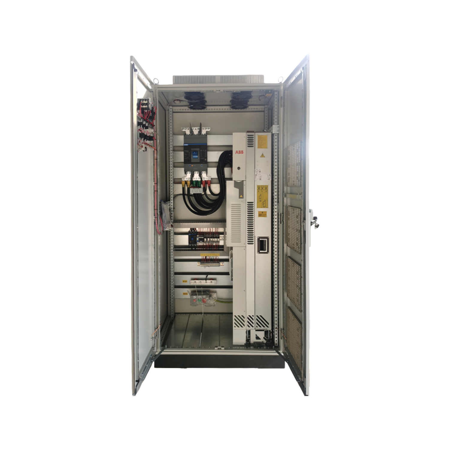
For an enclosed project, the Industrial VFD Panel page lists a modular arrangement, ventilation provisions, IP54 protection, built-in reactors, and RS485 or Ethernet communication options. Final component selection should still be based on the motor schedule, control philosophy, installation environment, and required electrical characteristics.
Separate Power and Control Wiring
Incoming power cables, drive output cables, braking conductors, analog signals, encoder wiring, and communication cables should not share an uncontrolled routing path. High-frequency switching from the drive output can couple electrical noise into sensitive circuits.
Use separate wiring ducts, tray sections, conduits, or internal barriers where practical. If power and signal conductors must cross, a near-right-angle crossing generally reduces the length over which coupling can occur.
Shielded motor cables can help contain high-frequency interference, especially where several drives operate in the same area or where instrumentation and communication networks are sensitive. Shield termination should follow the selected equipment instructions and the overall EMC design. A universal grounding rule should not be applied to every cable type.
Protective-earth connections should be short, secure, and low impedance. Bond the enclosure, mounting plate, drive chassis, filters, reactors, cable shields, and motor protective conductors as required. Painted or contaminated mounting surfaces should not be relied upon as the only bonding path.
Check Motor-Cable Length
Long motor cables can increase reflected-wave voltage at the motor terminals. This additional stress may affect motor insulation, bearings, and drive operation.
The permitted cable length depends on the drive, motor insulation, cable type, switching frequency, and installation method. Output reactors, dV/dt filters, or sine-wave filters may be required when the cable exceeds the recommended limit or when older motors are used.
Cable length becomes more complex in a parallel configuration because the drive supplies several branches. The designer should consider both the individual branch lengths and the total connected cable arrangement when evaluating output filtering.
Input harmonics should be assessed at the electrical system level. A line reactor may reduce current distortion in some applications, but the appropriate solution depends on transformer impedance, connected nonlinear loads, and measured harmonic levels. Where site measurements identify a broader power-quality issue, an Active Harmonic Filter Panel may be evaluated as part of the overall mitigation strategy.
Configure Multi-Motor Control and Switching Logic
A complete control philosophy should define where every command originates and which source has priority. A drive may receive commands from a local keypad, door-mounted controls, hardwired inputs, a programmable controller, or a supervisory system.
Local, off, remote, hand, and automatic modes should have clearly documented behavior. Operators must know whether a local command overrides automation, whether a communication failure stops the motor, and whether automatic restart is permitted after a power interruption.
The VFD Panel should not accept a start command until all required permissives are satisfied. Depending on the application, these conditions may include lubrication pressure, cooling airflow, valve position, guard status, downstream availability, or confirmation that the selected motor contactor is closed.
Parallel-Motor Logic
In a parallel system, all motors normally start, stop, and change frequency together. The control system should monitor individual overload contacts or temperature signals so that a faulted motor branch produces the required response.
The correct response may be to stop the complete group, isolate the affected motor, or generate an alarm while maintaining limited operation. That decision must be based on the mechanical process. Running the remaining motors after one branch stops can overload them or create uneven airflow, pressure, or material movement.
Individual contactors should not be opened casually while the shared drive is operating. If branch isolation during operation is necessary, the switching sequence and drive suitability must be specifically engineered.
Sequential-Motor Logic
For a sequential system, interlocking is essential. A practical sequence is:
Remove the run command.
Confirm that the drive output is disabled.
Open the active motor contactor.
Verify the open-position feedback.
Select the required motor parameter set.
Close the next motor contactor.
Verify the closed-position feedback.
Enable the drive and issue the run command.
Electrical interlocks should prevent two output contactors from closing simultaneously. Mechanical interlocks may provide an additional layer of protection where the contactor arrangement allows them.
The program should also define what happens if a contactor fails to open, fails to close, or produces contradictory feedback. The VFD Panel should block operation and generate a clear fault rather than continuing with an uncertain motor connection.
Acceleration and deceleration times should reflect the actual load inertia. Ramps that are too short can cause overcurrent or overvoltage trips, while unnecessarily long ramps may reduce production performance. Skip frequencies may be used where testing identifies mechanical resonance within the operating range.
Verify EU Compliance and Commission the System
Electrical equipment intended for the European Union must first satisfy the applicable legal directives. CE marking indicates conformity with the relevant EU requirements and should be supported by the appropriate assessment, technical documentation, and declaration.
Commissioning should verify the complete motor-drive system. Before energization, inspect conductor sizes, terminal torque, protective-device settings, grounding, cable shields, cooling paths, labels, interlocks, and drawing references. Confirm that every installed motor matches the approved schedule.
Functional testing should include:
Local and remote commands.
Acceleration and deceleration under load.
Individual motor overload protection.
Emergency-stop and safety functions.
Communication-loss behavior.
Power-loss and restart logic.
Sequential contactor interlocks.
Cooling-fan operation.
Enclosure temperature under normal load.
Alarm reporting and fault reset procedures.
For parallel motors, measure each branch current rather than relying only on the combined current shown by the drive. Unequal current can indicate differences in loading, motor condition, cable resistance, or mechanical alignment.
Record the final parameters, overload settings, communication addresses, firmware versions, and measured operating values. Updated schematics, terminal schedules, and operating descriptions should remain available for future troubleshooting.
Conclusion
A reliable VFD Panel begins with a clear definition of how every motor must start, stop, change speed, and respond to faults. Shared drives can suit compatible motors that always operate together, while independent or demanding loads usually require separate drives. Current-based sizing, individual motor protection, controlled output switching, thermal management, EMC-conscious wiring, and systematic commissioning should be treated as one coordinated design process. Zhejiang Zhegui Electric Co., Ltd. is a manufacturer of low- and medium-voltage distribution equipment whose panel manufacturing and customization capabilities can support application-specific motor-control and power-distribution requirements.
FAQ
Q: Can one VFD Panel operate several motors?
Yes. Compatible motors can share one drive when they run at the same frequency, but the drive must support the total current and every motor needs individual overload protection.
Q: How should a VFD Panel be sized for multiple motors?
Use the combined full-load current of all simultaneous motors, required overload duty, ambient derating, cable conditions, application torque, and the selected drive’s multi-motor limitations.
Q: Can motors connected to one drive run at different speeds?
No. Motors connected in parallel receive the same output frequency. Their actual shaft speeds may differ slightly because of load, slip, and motor characteristics.
Q: Can output contactors switch motors while a drive is running?
They should not switch without a specifically engineered procedure. The drive output should be disabled before a motor is connected or disconnected to prevent excessive current and equipment damage.
Q: When is one drive per motor preferable?
Separate drives are preferable when motors require independent speed, torque, starting, feedback, fault isolation, accurate synchronization, or continued operation after another motor stops.
Q: What EU requirements are relevant to a VFD Panel?
Applicable requirements may include CE marking, LVD 2014/35/EU, EMC 2014/30/EU, EN IEC 61439-1, and EN IEC 61439-2, depending on the completed assembly and application.