


An electrical distribution panel can meet its nominal voltage rating and still be unsuitable for the project. Incorrect load assumptions, inadequate fault ratings, poor cable access, and insufficient environmental protection may cause overheating, nuisance trips, difficult maintenance, or premature replacement. Selecting the right electrical distribution panel therefore requires more than comparing cabinet dimensions and breaker quantities. The decision should connect the building’s load profile, installation conditions, operating priorities, applicable EU requirements, and future expansion plans to a verified assembly specification.
Define the Panel’s Job in the Power Path
Begin by locating the panel within the single-line diagram. A general Low Voltage Distribution Board may receive power from an upstream board and distribute it to machinery, building services, or secondary circuits. The XL-21 configuration is intended for 380/660 V AC systems with rated current up to 630 A and can accommodate different incoming and outgoing cable arrangements. That type of electrical distribution panel may suit industrial or civil-building applications, but its suitability still depends on the project load, prospective fault current, protection scheme, and installation environment.
At the upstream end of a larger installation, a Main Distribution Board receives the principal low-voltage supply and divides it among major feeders. The MDB range is specified from 400 A to 4000 A at 380–690 V, with a 65 kA/1 s short-circuit rating, an IP54 enclosure, and separated busbar, breaker, and cable compartments. These characteristics address a different duty from that of a smaller downstream electrical distribution panel. Choosing between them requires a clear power hierarchy rather than simply selecting the cabinet with the largest current rating.
Near the final loads, a Lighting Distribution Panel organizes and protects branch circuits serving lighting zones and similar building loads. The configuration covers 63–250 A, 220–415 V, 50/60 Hz operation, IP54 protection, and EN IEC 61439-3 conformity. Its compact branch-circuit arrangement differs from the feeder architecture required at the service entrance. Defining the role first prevents an electrical distribution panel from being oversized electrically while remaining unsuitable functionally.
Size the Electrical Distribution Panel from Real System Data
The load schedule should drive the continuous current rating, not the sum of every connected nameplate. Record each outgoing circuit, operating current, duty cycle, starting behavior, phase arrangement, and expected coincidence with other loads. Apply diversity only where the operating pattern justifies it, then include reasonable allowance for approved future loads. An electrical distribution panel selected from an incomplete load schedule may be unnecessarily expensive or, more seriously, unable to carry the real operating load without excessive temperature rise.
Voltage and frequency are only the first electrical checks. The assembly’s rated current, incoming device, busbar capacity, neutral arrangement, and outgoing protective devices must work as a coordinated system. Loads with motors, variable-speed drives, electronic power supplies, or substantial single-phase demand may affect starting current, harmonic content, neutral loading, and heat generation. The electrical distribution panel should therefore be evaluated under its assembled operating conditions rather than by comparing individual component ratings taken from separate catalogs.
Prospective short-circuit current is another decisive input. The specified short-circuit withstand and protective-device breaking capacity must equal or exceed the calculated fault level at the installation point, considering the transformer, conductor impedance, and upstream network. Protection settings should also be coordinated so that a downstream fault is cleared as locally as practical instead of disconnecting the entire facility. A higher headline fault rating does not correct poor selectivity, and a suitable electrical distribution panel specification should address both withstand capability and protective coordination.
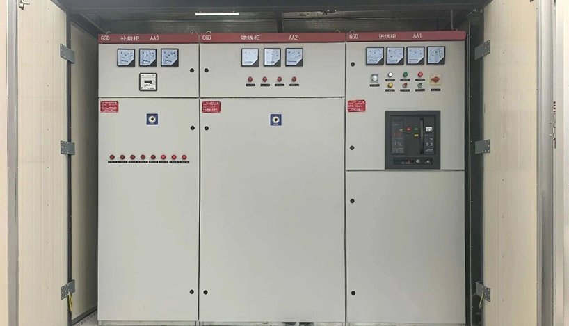
Temperature-rise performance must be considered together with the enclosure, ambient temperature, ventilation method, cable loading, and component arrangement. Free-air ratings do not automatically represent performance inside a closed cabinet containing several loaded circuits. Restricted airflow, nearby heat-producing equipment, high altitude, or high ambient temperature may require derating or a revised layout. The selected electrical distribution panel should have verified current ratings for the proposed configuration and service conditions, not merely a busbar described as large enough.
Match Protection and Construction to the Risk
CE Marking and ECM 1282
Electrical equipment placed on the European Economic Area market must meet the applicable EU market-access requirements. CE marking indicates that the manufacturer has evaluated the product and declares that it satisfies the relevant requirements for safety, health, environmental protection, and consumer protection. For an electrical distribution panel, the CE mark should be supported by complete technical documentation and an EU Declaration of Conformity covering the applicable requirements.
ECM, or Ente Certificazione Macchine, is an Italian notified body identified by number 1282. Documentation issued within its authorized scope can provide evidence of third-party technical assessment. Buyers should verify that any certificate clearly identifies the electrical distribution panel, model range, assessment basis, issuing organization, and validity period. The notified-body number alone does not confirm that the delivered assembly falls within the certificate’s approved scope.
LVD 2014/35/EU
LVD 2014/35/EU covers electrical equipment designed for operation between 50 V and 1000 V AC and between 75 V and 1500 V DC. Its safety requirements are intended to protect people, property, and domestic animals during normal operation and reasonably foreseeable use. An electrical distribution panel must therefore control risks such as electric shock, excessive temperature, fire, insulation failure, mechanical injury, and other hazards associated with electrical energy.
Compliance must be evaluated at assembly level rather than only through individual components. Clearances, creepage distances, protective bonding, barriers, conductor sizing, insulation, enclosure construction, and temperature-rise performance all influence the safety of the finished panel. CE-marked breakers, meters, and control devices do not by themselves establish conformity of the complete electrical distribution panel because their arrangement and interaction may introduce additional risks.
EMC 2014/30/EU
EMC 2014/30/EU addresses both electromagnetic emissions and immunity. Emissions from the equipment must not interfere with nearby communication systems, computers, controllers, or other sensitive devices. At the same time, the electrical distribution panel must withstand the electromagnetic disturbances expected in its intended environment without unsafe behavior, false signals, or unintended control actions.
Panels containing electronic meters, controllers, communication modules, variable-speed drive interfaces, or automated control equipment require careful attention to bonding, grounding, shielding, filtering, and cable segregation. Power conductors and sensitive signal cables should be arranged to limit electromagnetic coupling. EMC performance should be assessed for the completed electrical distribution panel rather than inferred solely from certificates supplied with individual electronic components.
EN IEC 61439 Series
The EN IEC 61439 series defines the principal technical requirements for low-voltage switchgear and controlgear assemblies used in European projects. EN IEC 61439-1 establishes general requirements covering temperature rise, dielectric properties, short-circuit withstand strength, protective circuits, clearances, enclosure protection, mechanical operation, and design verification. These requirements help demonstrate that the complete electrical distribution panel can operate safely within its declared ratings and service conditions.
EN IEC 61439-2 applies to power switchgear and controlgear assemblies, including many main power distribution applications. It focuses on current-carrying capability, temperature-rise performance, short-circuit behavior, mechanical construction, and verification of the completed assembly design. EN IEC 61439-3 applies to distribution boards intended to be operated by ordinary persons, with particular attention to accessibility, outgoing-circuit arrangements, safe operation, and protection against electric shock.
The applicable part of the EN IEC 61439 series should be selected according to the panel’s function and intended operator. A main distribution cabinet operated by trained personnel may require a different assessment basis from a smaller distribution board accessible to ordinary users. Project specifications should identify the applicable EN standard clearly instead of relying on general statements such as “compliant with international standards.”
Ingress protection should match the actual installation environment. EN 60529 classifies an enclosure’s protection against access, solid objects, and water. A higher IP rating is not automatically more suitable because increased sealing can restrict ventilation and affect internal temperature rise. The electrical distribution panel should therefore balance dust and moisture protection with thermal performance, cable-entry design, and maintenance access.
Internal separation should be determined by maintenance access, fault containment, and continuity requirements. Separating busbars, functional units, and cable terminals can reduce exposure to adjacent live parts and simplify certain maintenance tasks. However, additional separation also affects cabinet dimensions, ventilation, cable routing, inspection access, and cost. The required arrangement should reflect how the panel will be operated and which sections, if any, must remain energized during maintenance.
Enclosure material and surface treatment should suit the expected corrosion level, mechanical impact, indoor climate, and cleaning conditions. Hinges, locks, gaskets, barriers, supports, mounting plates, labels, and component spacing all influence long-term reliability and maintenance efficiency. A dependable electrical distribution panel results from coordinated electrical and mechanical design rather than cabinet thickness alone.
Plan Installation, Operation, and Expansion Together
A panel that performs well electrically can still create installation problems if physical constraints are ignored. Confirm the electrical room dimensions, transport route, floor loading, wall or floor mounting method, ventilation clearance, front and rear access, and required working space. Cable entry direction, conductor bending radius, gland-plate area, and termination height should be reviewed before production. These details determine whether the electrical distribution panel can be installed without unplanned cabinet modifications or unsafe cable bends.
Operating needs should shape the front layout and internal arrangement. Identify which breakers, meters, selector switches, alarms, and indicators operators need to see or control without opening energized compartments. Maintenance teams may also require removable covers, accessible terminals, test points, clear wire numbering, and enough space for torque tools or thermal inspection. An electrical distribution panel designed around actual tasks is easier to inspect and less likely to suffer wiring disturbance during routine service.
Metering and communication should be specified from a defined management objective. Basic projects may require only current, voltage, and energy values, while larger facilities may need feeder-level data, alarm outputs, or integration with a building management system. Communication protocol, network topology, addressing, auxiliary power, and cybersecurity responsibilities should be agreed before the equipment is built. Adding an intelligent meter alone does not make an electrical distribution panel useful unless the data can be accessed, interpreted, and maintained.
Expansion planning should cover both electrical and physical capacity. Spare outgoing ways have limited value when the main busbar, incomer, neutral, cable chamber, or enclosure cannot support additional load. Review the likely growth of lighting, HVAC, production equipment, renewable generation, storage, and backup supplies over the expected service period. The best allowance is based on a credible development plan rather than an arbitrary percentage that increases cost without solving a defined future requirement.
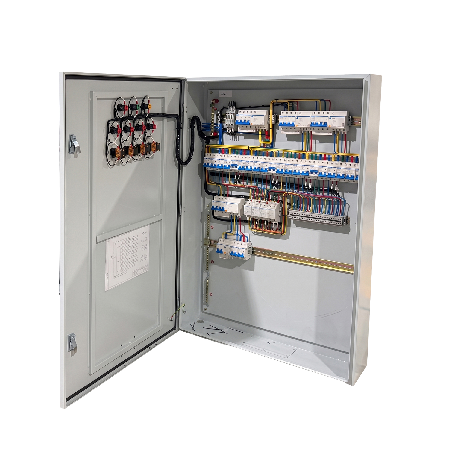
Lifecycle cost should include installation labor, interruption risk, inspection access, replacement-part availability, and future modification—not only the purchase price. A lower-cost electrical distribution panel may become expensive when cable chambers are too small, drawings are incomplete, or ordinary maintenance requires a full shutdown. Conversely, unnecessary monitoring, excessive separation, or an enclosure rating far beyond the environment can consume budget without improving the project. The right design spends money on verified risks and operating needs.
Verify the Assembly Before You Approve It
Technical documentation should be reviewed before the purchase order is finalized. A useful package normally includes the approved single-line diagram, general arrangement, circuit schedule, component list, terminal plan, cable-entry details, protection data, nameplate information, EU Declaration of Conformity, and applicable design-verification evidence. The documents should identify the proposed electrical distribution panel configuration rather than providing certificates for a different reference assembly. Design verification establishes the assembly design basis, while routine verification checks each completed unit before dispatch.
The final inspection should compare the built panel with the approved drawings and specification. Check component ratings, busbar arrangement, conductor identification, protective bonding, mechanical operation, interlocks, labels, clearances, and accessible terminations. Functional tests should confirm meters, indicators, control circuits, alarms, and communication interfaces where included. Any deviation affecting the electrical distribution panel rating, component compatibility, temperature rise, fault performance, EU compliance, or documentation should be resolved through controlled engineering review rather than informal substitution.
Supplier evaluation should examine engineering and production capability as well as the quotation. Useful evidence includes an identifiable factory, relevant processing and testing equipment, documented quality control, drawing-review procedures, and the ability to support project-specific assembly and inspection. Zhejiang Zhegui Electric operates its own production facilities with sheet-metal, busbar-processing, laser-cutting, welding, assembly, and testing equipment, providing direct manufacturing evidence for its panel range.
Conclusion
The right electrical distribution panel is defined by its system role, real load, fault level, environment, operating strategy, EU compliance, and verification records—not by cabinet size alone. Careful coordination of ratings, protection, access, cable space, thermal performance, and expansion capacity reduces redesign and lifecycle risk. Zhejiang Zhegui Electric Co., Ltd. is a manufacturer and supplier with its own production facilities for low- and medium-voltage distribution equipment. Its available panel configurations can support different positions in the distribution hierarchy when matched to an approved project specification.
FAQ
Q: What information is needed to specify an electrical distribution panel?
A: Provide the single-line diagram, load schedule, system voltage, fault level, installation environment, cable-entry requirements, protection philosophy, metering needs, and expected future expansion.
Q: How much spare capacity should an LV panel include?
A: There is no universal percentage. Reserve busbar capacity, outgoing ways, cable space, and enclosure room according to documented load growth and facility development plans.
Q: Is IP54 always better than IP30?
A: No. The IP rating should match dust and water exposure, while the complete enclosure must still provide suitable ventilation and verified thermal performance.
Q: What is the difference between an MDB and a lighting panel?
A: An MDB handles the principal incoming supply and major feeders, while a lighting panel distributes smaller downstream branch circuits serving lighting zones and related loads.
Q: Which EU requirements apply to an electrical distribution panel?
A: Applicable requirements may include the Low Voltage Directive 2014/35/EU, EMC Directive 2014/30/EU, CE marking obligations, and the relevant parts of EN IEC 61439.