


A fault in one medium-voltage cable should not force every connected transformer and building offline. However, maintaining supply continuity requires more than installing compact switchgear and assuming the network will automatically recover. The ring main unit, feeder arrangement, protection settings, cable system, operating procedures, and available alternative supply path must work together. This guide explains how ring main unit switchgear supports fault isolation, why its seven main benefits matter, and which electrical ratings, insulation technologies, safety features, installation conditions, and lifecycle requirements should guide a practical specification.
How a Ring Main Unit Keeps Power Available
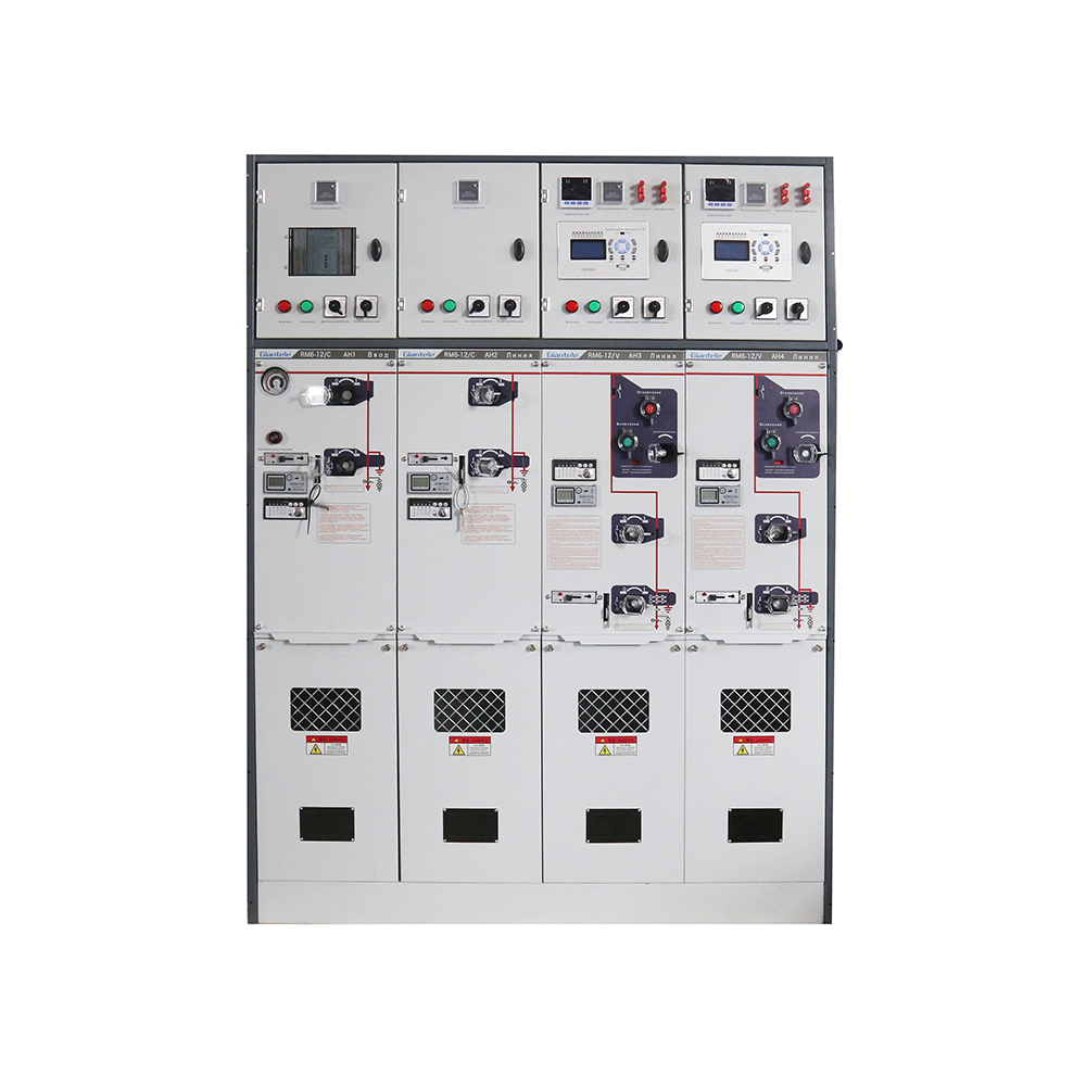
A ring main unit is compact medium-voltage switchgear positioned at an important connection point in a secondary distribution network. A typical arrangement includes two ring feeders and one or more transformer or load feeders. During normal operation, power travels through the available feeder path while switches control each network section. If a cable fault occurs, operators or an automated control system can open the switches on both sides of the affected section, isolate it, and restore healthy loads through the other side of the ring. This sectionalizing capability reduces the number of customers or processes affected by a single fault.
The unit normally combines load break switches, circuit breakers or switch-fuse combinations, earthing switches, busbars, cable terminations, mechanical interlocks, and operating indicators. Load break switches handle routine feeder switching, while circuit breakers or fuses protect selected outgoing circuits according to the network design. Earthing switches establish a safer condition for work after the circuit has been isolated and verified. A ring main unit is therefore one type within the broader switchgear category, not a replacement for every primary switchboard or high-capacity substation lineup. Relevant equipment ratings and construction requirements commonly fall within the EN IEC 62271 series for medium-voltage switchgear, controlgear, switches, and switch-disconnectors.
A ring arrangement also does not guarantee uninterrupted electricity by itself. Continuity depends on having an energized alternative path, adequate feeder capacity, selective protection, suitable switching procedures, and equipment that can safely interrupt or carry the expected current. An open radial system may use the same hardware without obtaining all the resilience associated with a closed-loop design. Project engineers should therefore evaluate the complete single-line diagram rather than judge reliability from the cabinet name alone.
Seven Powerful Benefits of Ring Main Unit Switchgear
The strongest benefits appear when the equipment configuration matches the protection study, operating environment, cable network, and restoration plan. Each advantage should therefore be treated as an engineering outcome rather than an isolated product feature.
Reliability and Restoration Benefits
1. Faster fault isolation. A ring main unit gives operators defined switching points on each side of a cable section. Instead of disconnecting an entire distribution branch, they can separate the damaged section and retain service on healthy feeders. Remote fault indicators, motorized mechanisms, relays, and communication equipment can further shorten fault-location and switching time, but automation must be coordinated with the protection philosophy.
2. Improved supply continuity. After isolation, loads may be transferred to the opposite side of the ring, provided that the alternative source and cables have sufficient capacity. This is especially valuable for urban networks, industrial facilities, commercial developments, utilities, transportation infrastructure, and other sites where a lengthy outage would have operational consequences. The benefit is reduced outage scope rather than absolute immunity from power interruption.
Space, Safety, and Maintenance Benefits
3. A smaller installation footprint. Compact construction allows several switching and protection functions to occupy less space than a large conventional lineup. This can simplify secondary substation design where floor area, access corridors, cable routing, or building modifications are constrained. Space savings should still be assessed together with required working clearances, pressure-relief arrangements, cable-bending radii, and future access.
4. Safer switching and isolation. Enclosed live components, mechanical interlocks, clear position indicators, earthing switches, and controlled operating sequences reduce opportunities for accidental contact and incorrect operation. These features do not replace lockout procedures, voltage testing, personal protective equipment, or trained personnel. Their value is that the physical design helps reinforce the intended safety process.
5. A lower routine maintenance burden. Sealed gas-insulated designs protect primary conductors and switching components from dust, humidity, pollution, and other external contamination. Internal cleaning and adjustment may therefore be reduced compared with exposed air-insulated equipment. Nevertheless, maintenance teams must still inspect mechanisms, cable terminations, control circuits, relays, indicators, enclosure condition, earthing connections, and any applicable gas-monitoring devices.
Planning and Control Benefits
6. Flexible network expansion. Modular arrangements allow designers to combine incoming feeders, outgoing feeders, transformer protection, metering, and circuit-breaker functions according to the single-line diagram. Extensible equipment can support later network changes without replacing every existing panel. This flexibility has the greatest value when future load growth, spare cable routes, bus ratings, installation space, and compatible extension interfaces are considered before purchase.
7. Better monitoring and remote control. A ring main unit can be equipped with motorized operation, protection relays, fault passage indicators, sensors, remote terminal units, and communication interfaces. Operators can then view status information and perform approved switching without waiting for personnel to reach every substation. Successful automation still requires a reliable control power supply, cybersecurity planning, communication compatibility, accurate point lists, and tested local manual operation.
Match the Insulation and Feeder Architecture to the Site
Gas-Insulated Designs
Gas-insulated equipment encloses primary energized components within a sealed chamber, producing a compact structure with strong resistance to environmental contamination. It is frequently considered for restricted spaces, humid locations, underground distribution rooms, coastal projects, and substations where reducing internal maintenance access is important. The 12kV Gas-Insulated RMU, for example, has a rated current of up to 630 A, a 50 Hz frequency, IP67 protection, front operation, and configurable load-switch, fuse, vacuum-switch, and circuit-breaker modules. These are product-specific characteristics and should be checked against the final approved technical schedule.
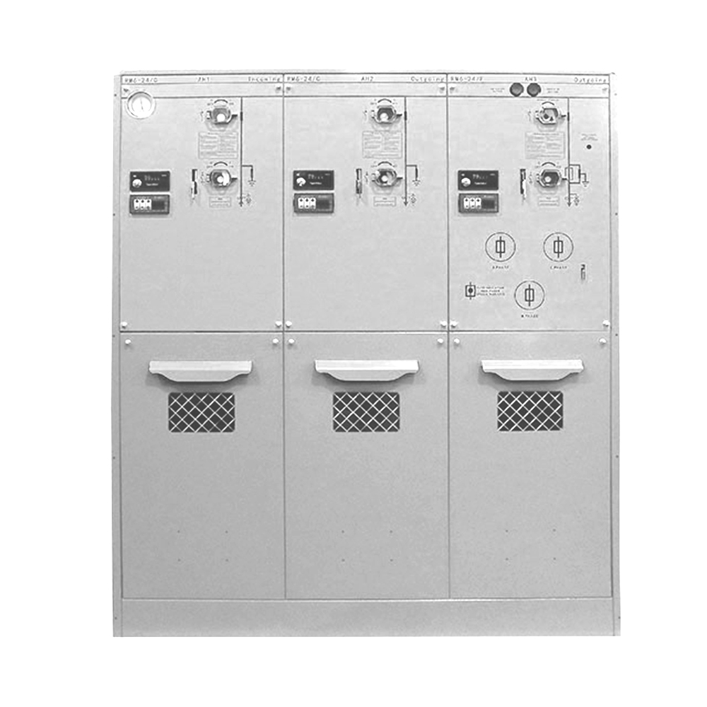
Voltage class must be selected independently from physical appearance or cabinet configuration. The 24kV SF6 Ring Main Unit has a 24 kV rated voltage, 630 A rated current, 50 Hz frequency, IP67 protection, a sealed enclosure, interlocking, pressure-relief provisions, and modular functional units. Those published values illustrate why the same general switchgear format cannot automatically be applied across different system voltages. Insulation levels, cable interfaces, protection duties, clearances, and test documentation must correspond to the actual project.
Air- and Solid-Insulated Alternatives
Air-insulated equipment avoids the use of insulating gas and can provide accessible construction, but it normally requires more space and may need greater attention to dust, moisture, condensation, and clearance conditions. Solid-insulated designs use dielectric materials around energized components and can offer a compact gas-free option. Selection should consider repair philosophy, local technical support, environmental exposure, end-of-life handling, procurement rules, and the owner’s standardization policy instead of focusing only on initial price.
Environmental regulation is also becoming a direct specification issue. Requirements differ by market, and current European Union rules include restrictions affecting certain new medium-voltage switchgear that uses fluorinated greenhouse gases, with dates, voltage ranges, and defined exceptions set by Regulation (EU) 2024/573. Buyers should confirm the rules applicable at the equipment destination before approving an insulation technology or assuming that an existing specification remains acceptable.
Feeder and Protection Configuration
The required arrangement may include two load-switch ring feeders and one transformer feeder, multiple circuit-breaker feeders, metering functions, or an extensible combination of several modules. A fuse-switch combination can be appropriate for some transformer protection duties, while a circuit breaker with a relay provides adjustable protection and may be preferable where coordination, remote tripping, or more detailed fault response is required. The decision should follow fault-current calculations, transformer characteristics, cable ratings, selectivity requirements, and the utility’s protection rules.
Specify a Ring Main Unit Without Missing Critical Ratings
A useful specification connects every requested feature to a network condition or operational need. Copying a previous bill of materials can create serious mismatches when the new site has a different voltage, fault level, transformer size, cable type, altitude, humidity, or control system. At a minimum, the purchaser and manufacturer should review the single-line diagram, load data, short-circuit study, protection philosophy, installation layout, cable schedule, automation architecture, and applicable standard before production begins.
Specification Item | What to Verify | Why It Matters |
|---|---|---|
Rated voltage and insulation level | System maximum voltage, power-frequency withstand, and impulse withstand | Prevents insulation mismatch and supports coordination with the network |
Continuous current | Feeder, busbar, transformer, and expected future load current | Avoids overheating and unnecessary oversizing |
Short-circuit duty | Breaking, making, peak withstand, and short-time withstand ratings | Confirms that the unit can safely manage the calculated fault level |
Feeder functions | Load switches, fuses, circuit breakers, earthing switches, and metering | Aligns each panel with its switching and protection duty |
Safety classification | Interlocks, pressure relief, accessibility, enclosure protection, and internal-arc requirements | Protects personnel and influences room layout |
Cable interfaces | Cable size, termination type, entry direction, number of cables, and test access | Prevents installation delays and inaccessible connections |
Controls and communication | Motorization, relays, auxiliary voltage, indications, protocol, and remote terminal unit signals | Enables reliable automation and system integration |
Service conditions | Temperature, altitude, humidity, pollution, seismic conditions, and indoor or outdoor installation | Identifies necessary design adjustments before manufacture |
The rated voltage or current alone is not sufficient evidence of suitability. A project can still fail if its short-circuit rating is inadequate, cables cannot enter the compartment, relay settings cannot coordinate with upstream protection, or pressure relief conflicts with the building design. Documentation should include approved drawings, technical data, schematic diagrams, interlocking logic, routine test records, relay information, cable-interface details, installation instructions, and an agreed list of accessories. EN IEC 62271-200 addresses factory-assembled metal-enclosed switchgear above 1 kV and up to 52 kV, while related parts of the EN IEC 62271 series cover the individual switching functions used within the assembly.
Installation and Lifecycle Practices That Protect the Benefits
Before installation, the site team should confirm the foundation dimensions, access route, room ventilation, earthing system, cable trenches, environmental conditions, and pressure-relief direction. Equipment should be checked for shipping damage, moisture entry, loose components, and correspondence with approved drawings. Commissioning normally includes mechanical operation, interlock verification, contact and circuit checks, cable testing, earthing confirmation, protection testing, control-power checks, and validation of local and remote indications. The exact sequence must follow the manufacturer’s instructions, project procedures, and applicable safety rules.
A sealed ring main unit should not be interpreted as equipment that can be ignored for its entire service life. External corrosion, damaged door seals, abnormal indications, contaminated cable compartments, loose secondary wiring, control-battery problems, worn mechanisms, incorrect relay settings, and deteriorating cable terminations can still affect reliability. Inspection intervals should reflect operating frequency, environmental severity, utility policy, fault history, and product documentation rather than a universal schedule. Any work involving insulating gas must also follow local environmental, recovery, personnel-certification, and handling requirements.
Lifecycle planning should begin during procurement. Operators need accessible drawings, spare-part identification, protection files, communication maps, training records, and clear switching instructions. Factory acceptance testing can verify construction, wiring, interlocks, operation, and specified electrical tests before shipment, while site acceptance confirms correct integration with cables, transformers, protection, and control systems. Zhejiang Zhegui Electric’s production stages include enclosure production, assembly, wiring, testing, and packing. Customers may also participate in manufacturing-quality inspections and delivery testing.
Conclusion
A ring main unit delivers its greatest value when compact construction is combined with the correct network topology, electrical ratings, protection scheme, cable interfaces, interlocks, and operating procedures. Buyers should evaluate the complete distribution system rather than selecting equipment by voltage or cabinet size alone. Zhejiang Zhegui Electric Co., Ltd. is a manufacturer of low- and medium-voltage electrical equipment with production, assembly, wiring, testing, and customization activities. Its ring main unit products can support reliable project design when their verified specifications are matched carefully to actual site and network requirements.
FAQ
Q: Is a ring main unit the same as switchgear?
A: A ring main unit is a compact type of medium-voltage switchgear designed for sectionalizing, protection, and control in ring or radial distribution networks.
Q: Does an RMU guarantee uninterrupted power?
A: No. It supports faster isolation and alternative feeding, but continuity still depends on network topology, source availability, feeder capacity, protection coordination, and operating procedures.
Q: What is the difference between gas- and air-insulated RMUs?
A: Gas-insulated units are generally more compact and environmentally sealed, while air-insulated designs usually require more space and greater protection from contamination and moisture.
Q: Which ratings are most important when selecting a ring main unit?
A: Verify rated voltage, continuous current, insulation level, short-circuit breaking and withstand duties, feeder configuration, enclosure protection, cable interfaces, and service conditions.
Q: Can a ring main unit be operated remotely?
A: It can support remote operation when equipped with compatible motor mechanisms, relays, sensors, control power, communication devices, and correctly engineered automation logic.