


Medium-voltage distribution failures are rarely caused by one missing feature. They usually begin with a mismatch among network topology, fault level, protection, insulation, and operating procedure. Ring Main Unit Switchgear brings switching, isolation, earthing, and transformer-feeder protection into a compact assembly, but similar-looking units can have very different duties and lifecycle obligations. A sound specification must therefore consider how the ring is operated, how faults are cleared, what environmental conditions exist, and who will maintain the equipment. The following guidance turns those decisions into a practical selection and operating framework.
How Ring Main Unit Switchgear Supports Service Continuity
A ring distribution network gives a group of substations or loads access to more than one potential supply path. In a common arrangement, the cables form a physical loop while one switching point remains normally open. This avoids unintended parallel operation while preserving an alternative route that can be used after a fault. Ring Main Unit Switchgear provides the sectionalizing points needed to disconnect the damaged cable section, earth it when required, and restore healthy sections from the other side of the network. The equipment improves continuity by enabling controlled isolation; it does not guarantee an uninterrupted supply by itself.
The restoration process may be manual, remotely controlled, or automated. In a basic installation, qualified operators identify the faulted section and follow an approved switching schedule. A more advanced installation may add motorized mechanisms, fault passage indicators, protection relays, communication equipment, and SCADA integration. These functions reduce fault-location time and allow control centers to operate selected ring switches remotely, but protection coordination must still prevent an alternative feed from energizing an uncleared fault. Utilities use targeted remote control and relay-grade fault information specifically to improve fault isolation and supply restoration.
This distinction matters during procurement. Buyers sometimes request an “automatic RMU” without defining the desired control logic, communication protocol, power supply, indication signals, or responsibility for system integration. Ring Main Unit Switchgear should instead be specified as part of a complete network operating philosophy. The single-line diagram must show normal switch positions, source locations, transformer feeders, protection zones, and the normal open point. Without that information, adding motors and communication devices may increase cost without delivering dependable automated restoration.
Components That Determine Protection and Operator Safety
The ring feeder usually uses a load break switch designed to make and break normal load current. A transformer feeder may use a switch-fuse combination or a vacuum circuit breaker with a protection relay. Fuses can provide economical transformer protection when their ratings coordinate correctly with transformer inrush, cable limits, and downstream devices. Circuit breakers offer resettable protection and more flexible relay functions, making them useful where fault levels, transformer capacity, automation, or selectivity requirements are more demanding. The busbar, cable terminations, operating mechanisms, and auxiliary circuits must all match the electrical duty rather than being treated as secondary accessories.
Earthing switches and mechanical interlocks are equally important. A three-position mechanism may provide service, isolated, and earthed positions, reducing the chance of incompatible switching states. However, an interlock is an engineering safeguard, not permission to bypass operating rules. Voltage indication, test access, mimic diagrams, position indicators, pressure or insulation monitoring, and clear cable-compartment access all affect how safely technicians can confirm equipment status. EN IEC 62271-200 covers metal-enclosed switchgear assemblies above 1 kV and up to 52 kV, while EN IEC 62271-103 addresses AC switches and switch-disconnectors within the same voltage range.
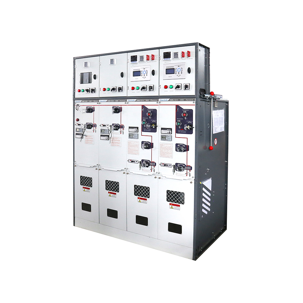
A practical example is the SF6 Ring Main Unit, which is designed for 12 kV, 50 Hz service with 630 A or 1,250 A rated-current options. Its live parts and switching devices are enclosed in a sealed stainless-steel chamber, and the product supports fixed or expandable combinations using load-switch, fuse, vacuum-switch, and circuit-breaker functions. The sealed system has an IP67 protection level, and optional electric operating mechanisms are available for remote-control applications.
Choosing the Insulation System and Configuration
Insulation choice affects dimensions, environmental obligations, maintenance practices, and end-of-life handling. SF6-insulated equipment can provide a compact, stable sealed design, especially where space and external contamination are major concerns. However, SF6 requires controlled handling because it is a highly persistent greenhouse gas with a 100-year global warming potential thousands of times greater than carbon dioxide. Regulations and purchasing policies are therefore accelerating the use of alternative insulation technologies.
Insulation Approach | Main Benefit | Key Consideration |
|---|---|---|
SF6-sealed design | Compact construction and strong separation from external contamination | Gas monitoring, recovery, regulatory compliance, and end-of-life treatment |
Dry-air or nitrogen design | Avoids SF6 while retaining a sealed insulation chamber | Dimensions, pressure design, temperature range, and verified dielectric performance |
Solid or hybrid insulation | Reduces or eliminates insulating gas requirements | Surface condition, material aging, partial-discharge control, and repair strategy |
Conventional air insulation | Familiar inspection and maintenance access | Greater clearance and installation-space requirements |
The SF6-Free Air RMU provides an example of an alternative 12 kV design. It is rated at 630 A and uses dry air or nitrogen for insulation together with vacuum arc interruption. It has a sealed enclosure rated IP67, modular circuit-breaker and load-switch combinations, mechanical interlocking, and optional current-transformer arrangements for protection and distribution automation. These details illustrate why “SF6-free” is only one selection criterion; the buyer must still verify ratings, enclosure design, switching duty, protection functions, and environmental conditions.
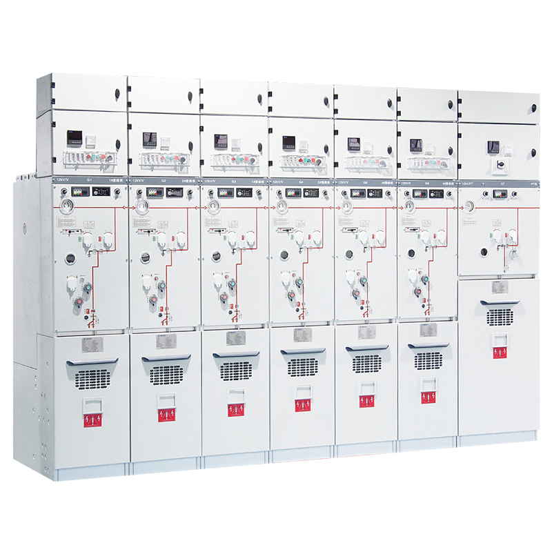
Configuration must also match the feeder arrangement. A typical three-way unit may contain two ring switches and one transformer feeder, while larger systems add outgoing feeders, metering sections, or circuit-breaker modules. Extendable Ring Main Unit Switchgear is useful where future feeders are likely, but expansion interfaces, busbar ratings, available room, and permitted outage procedures must be established before installation. A non-extendable assembly can be more compact for a fixed scheme, yet later network changes may require replacement instead of adding one module.
How to Specify Ring Main Unit Switchgear
Begin with the network data rather than a preferred cabinet model. The request for quotation should state nominal system voltage, the required equipment voltage class, frequency, system earthing method, maximum operating current, prospective short-circuit current, fault duration, peak withstand requirement, and insulation levels. A unit with sufficient load current may still be unsuitable if its short-time withstand rating is below the calculated fault level. Likewise, the transformer feeder must be selected from the transformer rating, impedance, inrush behavior, cable limits, and required protection coordination—not from transformer capacity alone.
The RM6 Gas Switchgear link resolves to a 12 kV gas-insulated design offering modular C, F, V, and circuit-breaker functions. Its electrical characteristics include 42/48 kV power-frequency withstand levels, 75/85 kV lightning impulse withstand levels, and different mechanical-life values according to module type. These figures demonstrate why procurement documents should identify the exact functional unit being evaluated. A bus coupler, ring switch, fuse way, and circuit-breaker feeder may share an enclosure family but have different current-interruption and mechanical-endurance duties.
Site conditions come next. Specify indoor or outdoor installation, minimum and maximum ambient temperature, altitude, humidity, condensation, salt contamination, dust, flooding exposure, seismic requirements, and ventilation. Altitude can require insulation correction, while high humidity and contamination influence creepage distance, enclosure protection, heaters, and sealing. Cable information should include conductor material, cross-section, number of cables per phase, termination interface, bending radius, entry direction, screen-earthing arrangement, and test access. Many installation delays occur because the electrical ratings are correct but the cable compartment cannot accommodate the selected termination.
Automation requirements should be written as measurable interfaces. Define which switches require motor operation, whether local and remote modes are needed, auxiliary-contact quantities, control voltage, trip and close commands, communication protocol, event recording, fault indication, and cybersecurity responsibilities. Ring Main Unit Switchgear may also require current transformers, voltage sensors, protection relays, metering, and a remote terminal unit. Each device must have adequate accuracy, burden, ratio, and environmental rating for its function. A vague request for “smart grid readiness” does not establish who supplies the control panel, programs the relay, tests communications, or validates the restoration sequence.
Finally, request drawings, routine-test records, type-test evidence applicable to the offered construction, operating manuals, foundation details, cable-interface drawings, and spare-parts recommendations. Confirm whether the tested arrangement covers the actual number of panels, internal-arc classification, accessibility type, and installation direction required by the project. EN IEC 62271-200 applies to prefabricated metal-enclosed assemblies for indoor or outdoor service above 1 kV and up to 52 kV, but the project specification must still identify the classifications and ratings needed.
Safe Operation, Inspection, and Lifecycle Planning
Only qualified personnel should operate or maintain Ring Main Unit Switchgear, using an approved single-line diagram and site-specific switching schedule. Before work, every possible source must be identified, disconnected, secured against reconnection, and verified de-energized with suitable test equipment. Earthing must then be applied where required by the equipment design and local safety rules. Mechanical interlocks, position indicators, and control switches must never be treated as substitutes for isolation, lockout or tagging, absence-of-voltage testing, and control of stored energy. Electrical-safety requirements call for de-energized circuits to remain secured and verified before exposed parts are approached.
Routine inspection should follow the manufacturer’s instructions and the equipment’s insulation technology. Useful checks may include enclosure condition, corrosion, moisture entry, cable-termination condition, mechanism operation, position indication, heater function, auxiliary power, relay alarms, and insulation- or gas-monitoring indications. Maintenance-free sealed chambers reduce scheduled internal work, but they do not eliminate inspection of external mechanisms, cables, controls, protection settings, or the installation environment. Lifecycle planning should also address operator training, diagnostic testing, replacement modules, fuse availability, relay support, gas recovery where applicable, and decommissioning responsibilities.
Conclusion
Selecting Ring Main Unit Switchgear requires more than matching voltage and current. The network topology, fault level, feeder-protection method, insulation system, cable arrangement, automation scope, site environment, and operating procedures must work as one coordinated design. Zhejiang Zhegui Electric Co., Ltd. is a manufacturer of low- and medium-voltage power-distribution equipment with verified production and OEM capabilities. Its gas-insulated and SF6-free RMU options can support different project priorities when their ratings and configurations are checked against the actual distribution system, regulatory requirements, and lifecycle plan.
FAQ
Q: What is the main purpose of Ring Main Unit Switchgear?
A: It provides compact medium-voltage switching, fault isolation, earthing, and transformer-feeder protection while allowing healthy network sections to be supplied through an alternative route.
Q: Does an RMU automatically restore power after a fault?
A: Not always. Restoration may require manual switching unless the unit includes motorized mechanisms, fault indicators, communications, and an approved remote or automatic control scheme.
Q: Is SF6-free switchgear always air-insulated?
A: No. SF6-free equipment may use dry air, nitrogen, solid dielectric materials, vacuum interruption, or a hybrid insulation system depending on its construction.
Q: What ratings are essential when specifying an RMU?
A: Confirm voltage class, rated current, short-time and peak withstand current, insulation levels, switching duties, internal-arc requirements, environmental limits, and cable interfaces.
Q: What is a typical three-way RMU configuration?
A: It commonly includes two ring feeder switches and one transformer feeder protected by a fuse-switch combination or a circuit breaker and protection relay.
Q: Can Ring Main Unit Switchgear be expanded later?
A: An extendable design can accept additional compatible modules, but the expansion interface, busbar rating, available space, and future outage arrangements must be planned initially.