


Introduction
In modern electrical systems, capacitor banks improve power factor, reduce losses, and maintain system voltage stability. However, when capacitor banks are installed without proper harmonic mitigation, they can unintentionally create resonance points and lead to severe equipment failures or power quality issues. To avoid these challenges, reactors (also called detuning reactors or harmonic filters) are commonly paired with capacitor banks. This pairing improves reliability and keeps industrial and commercial networks running safely.
This article provides an in-depth look at why reactors are used with capacitor banks, how they work, and the benefits they deliver in modern electrical systems.
Understanding the Purpose of a Capacitor Bank in Power Systems
A capacitor bank is an assembly of multiple capacitors connected in series or parallel to store and discharge reactive power as needed. The main function of a capacitor bank is to improve the power factor, the ratio of real power to apparent power in an AC circuit. When a system operates with a low power factor, it draws more current for the same load, leading to inefficiency, voltage drops, and higher utility costs.
Common Functions of Capacitor Banks
| Function | Description | Benefit |
|---|---|---|
| Power Factor Correction | Reduces reactive power drawn from the grid | Lowers electricity bills |
| Voltage Support | Stabilizes voltage levels under heavy load | Improves supply reliability |
| Load Balancing | Manages uneven distribution across phases | Reduces system stress |
| Loss Reduction | Decreases transmission losses | Enhances efficiency |
However, when these banks are installed in power networks that contain nonlinear loads such as variable frequency drives (VFDs), inverters, or rectifiers, the capacitor bank alone becomes vulnerable to harmonics. This is where reactors become essential.
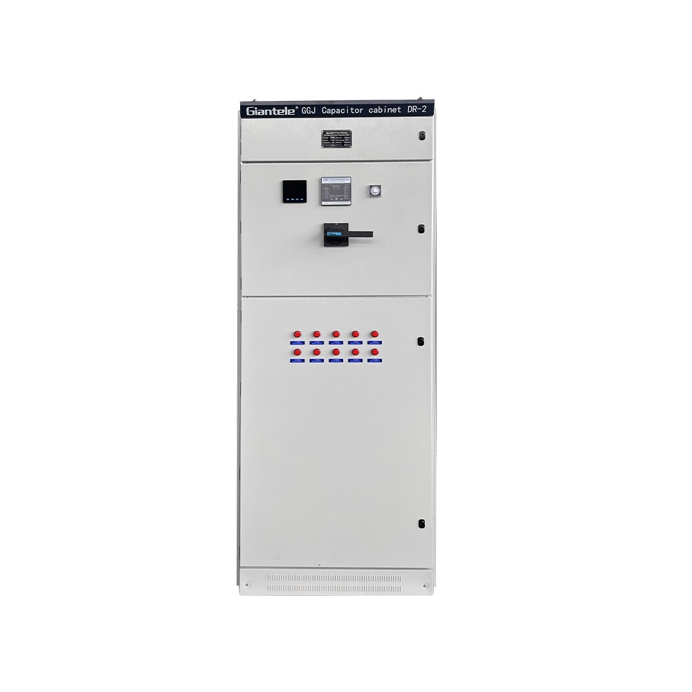
The Role of Reactors in Electrical Circuits
A reactor is an inductive component that resists sudden changes in current. In capacitor bank applications, reactors are specifically designed to limit inrush currents, block harmonics, and tune the overall system away from resonant frequencies.
There are two main types of reactors associated with capacitor banks:
Series Reactors (Detuning Reactors). Connected in series with each capacitor branch.
Harmonic Filter Reactors. Designed to create a specific impedance path for harmonic frequencies, diverting them safely to ground.
By combining inductance (from the reactor) and capacitance (from the capacitor bank), the system can achieve a stable, controlled impedance profile that minimizes distortion and resonance.
Why Reactors Are Essential for Capacitor Banks
When capacitor banks are connected to a power network with harmonics, they can unintentionally amplify those harmonic currents. This happens because the combination of system inductance and capacitance can create a resonant circuit. At the resonant frequency, even small harmonic currents can cause large voltage and current surges, damaging capacitors, circuit breakers, and transformers.
Reactors help by:
Detuning the capacitor bank to a frequency below the dominant harmonic order.
Preventing resonance between the system inductance and the capacitor bank.
Limiting inrush current during capacitor switching operations.
Protecting sensitive electrical components from overheating and failure.
Resonance and Detuning Explained
| Parameter | Without Reactor | With Reactor |
|---|---|---|
| Resonant Frequency | Matches with harmonic order (dangerous) | Shifted below harmonic range |
| Harmonic Current Flow | Amplified | Suppressed |
| Capacitor Life | Shortened | Extended |
| Voltage Distortion | Severe | Controlled |
By adding reactors, the system's resonant frequency is shifted to a safer range (commonly 189 to 215 Hz for a 50 Hz system). This configuration is called a detuned capacitor bank.
The Working Principle of a Reactor-Capacitor Bank Combination
When a reactor is installed in series with a capacitor bank, the combined impedance at harmonic frequencies becomes predominantly inductive. This ensures that harmonic currents do not flow into the capacitor bank but are instead damped by the reactor's inductive reactance.
Step-by-Step Working Process:
The reactor is placed in series with each step of the capacitor bank.
The reactor creates an inductive voltage drop that opposes harmonic frequencies.
The overall system's resonant frequency shifts below the lowest significant harmonic (commonly the 5th harmonic).
The result is smoother current flow, improved voltage stability, and prolonged equipment lifespan.
The reactor's inductance value (typically 5.67%, 7%, or 14%) determines how much detuning or filtering is achieved. Choosing the correct tuning percentage is critical for balancing cost, performance, and harmonic mitigation.
Benefits of Using Reactors with Capacitor Banks
The inclusion of reactors transforms a standard capacitor bank into a harmonic-resistant power conditioning unit. The advantages are technical and commercial.
1. Enhanced System Reliability
Reactors protect capacitors from harmonic overloading and overvoltage conditions, reducing the likelihood of premature failure. This ensures longer maintenance cycles and fewer shutdowns.
2. Harmonic Mitigation
Reactors limit the harmonic current entering the capacitor bank, maintaining the system's total harmonic distortion (THD) within acceptable limits as per IEEE 519 or IEC standards.
3. Controlled Switching and Inrush
When capacitors are switched on, a surge of inrush current occurs. Reactors limit these currents, preventing contactor damage and mechanical stress.
4. Improved Voltage Stability
By controlling harmonics and reactive power flow, the overall voltage profile across the network remains more stable, even under dynamic load conditions.
5. Extended Equipment Life
Capacitors, transformers, and cables operate under lower electrical stress when harmonics are mitigated, improving their operational longevity.
Choosing the Right Reactor for a Capacitor Bank
Selecting an appropriate reactor requires a balance between cost, detuning percentage, and harmonic profile of the electrical system.
| Reactor Rating | Detuning Frequency (50 Hz) | Resonant Order | Common Application |
|---|---|---|---|
| 5.67% | 210 Hz | 4.20 | General harmonic reduction |
| 7% | 189 Hz | 3.78 | Heavy industrial loads |
| 14% | 134 Hz | 2.67 | High distortion environments |
Key Factors to Consider
System Voltage and Frequency: Must match the operating conditions.
Harmonic Spectrum: Identifies dominant harmonic orders.
Capacitor Bank Size: Determines required reactor inductance.
Thermal Capacity: Ensures the reactor can handle harmonic currents without overheating.
Correct sizing and simulation decide how well the reactor-capacitor combination performs.
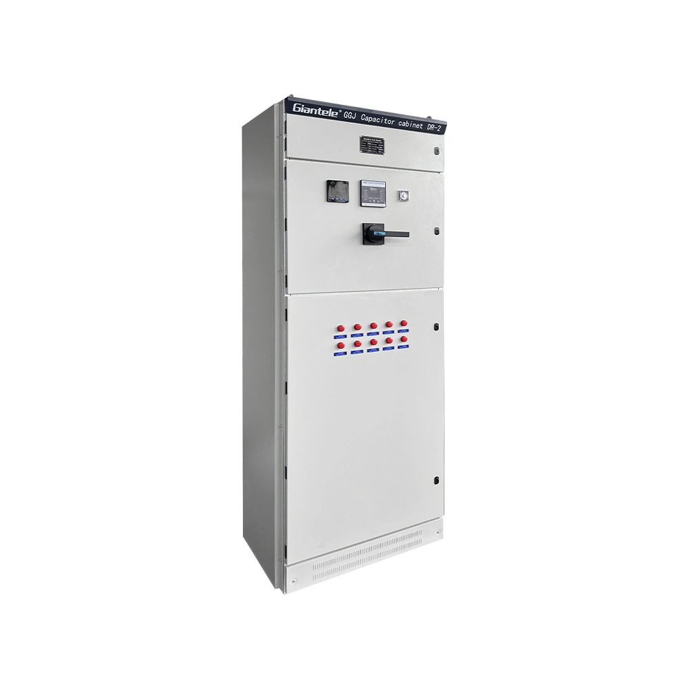
Practical Applications in Modern Power Systems
Reactor-equipped capacitor banks are used across multiple sectors, especially where harmonic-rich loads are present.
Common Applications
Industrial Plants: VFDs, welding machines, induction furnaces.
Commercial Buildings: Elevators, HVAC systems, lighting controllers.
Renewable Energy Systems: Solar inverters and wind turbine converters.
Data Centers: UPS systems and power electronic converters.
In these environments, reactors ensure that the capacitor banks function efficiently without contributing to power quality problems.
Comparison: Capacitor Bank with vs. without Reactor
| Feature | Without Reactor | With Reactor |
|---|---|---|
| Power Factor Correction | Effective | Effective |
| Harmonic Filtering | None | Significant |
| Resonance Risk | High | Low |
| Equipment Protection | Limited | Strong |
| Maintenance Frequency | High | Low |
| Overall System Life | Shorter | Longer |
Reactors add initial cost. The lower maintenance and longer equipment life usually repay it within a few years.
Maintenance and Operational Best Practices
Even with reactors installed, maintenance remains crucial to ensure optimal performance of capacitor banks.
Recommended Practices
Regular Inspection: Check for overheating, loose connections, and insulation wear.
Capacitor Health Monitoring: Measure capacitance values and compare with rated specifications.
Harmonic Measurement: Periodically test THD levels to ensure compliance.
Reactor Condition Checks: Look for signs of vibration or humming, which may indicate magnetic core issues.
These checks keep capacitors and reactors working through years of service.
Conclusion
Reactors are essential for enabling capacitor banks to operate safely and efficiently in modern electrical systems. By mitigating harmonics, preventing resonance, and controlling inrush currents, reactors extend the life of capacitors and protect the entire network from instability and failures.
The integration of reactors transforms capacitor banks from simple power factor correction devices into comprehensive power quality solutions, making them indispensable in today's power electronics-driven environments.
Sizing a Detuned Bank for an Existing Switchroom
Most enquiries we receive are for replacing an existing compensation panel, not for a greenfield installation. The panel is already sized, the switchroom is already built, and the goal is to stop capacitor failures without rebuilding the room.
Three measurements decide the answer.
Existing bank rating in kvar. The reactor must match the capacitor step it sits on, not the total bank.
Dominant harmonic order. A plant with only 5th harmonic loads usually takes a 7% reactor. A plant with 3rd harmonic from single-phase loads needs 14%, because 7% would leave the 3rd harmonic unprotected.
Available cubicle depth. A detuned reactor adds roughly 20 to 35 percent to the volume of each capacitor step. If the existing cubicle cannot take it, the steps have to be split across more cubicles.
Where the existing panel is too shallow, we build replacement cubicles to the original footprint so the new steps drop into the same cable trench and busbar position. The outgoing cables and the switching schedule stay as they are.
How to Check a Detuned Bank After Commissioning
Detuned banks fail quietly. A reactor that has lost part of its winding still passes current, and the capacitor still switches in. The fault only shows up as heat or as an audible change.
Listen for a change in tone. A healthy reactor hums at a steady 100 Hz. A rising or rattling note points to loose laminations.
Measure the case temperature monthly. Record it against the day of commissioning. A rise of more than 15 K over the baseline is a warning sign.
Compare step capacitance yearly. A step that has drifted more than 5 percent from its rated value will distort the tuning of the whole branch.
A 7% detuned reactor sits on the border between IEEE 519 and IEC limits, so ask for the resonant order in writing before you accept a quotation.
Keep the commissioning readings on file. Without a baseline, a later measurement tells you the temperature but not whether it has changed.
FAQ
What happens if a capacitor bank is used without reactors?
Without reactors, capacitor banks can experience resonance with system inductance, amplifying harmonic currents and causing capacitor or fuse failure.
What is the typical detuning percentage for reactor-capacitor systems?
Common detuning values are 5.67%, 7%, and 14%, depending on the harmonic environment and application type.
Can reactors completely eliminate harmonics?
Reactors primarily limit and shift harmonics rather than eliminate them entirely. For full mitigation, active harmonic filters may be used alongside reactors.
Are reactors necessary for all capacitor banks?
Not always. In clean power systems with minimal harmonic distortion, reactors may not be required. However, in most modern installations with nonlinear loads, they are strongly recommended.
How often should reactor-capacitor systems be maintained?
A preventive maintenance check every 6 to 12 months is ideal, focusing on temperature, insulation, and electrical connections.