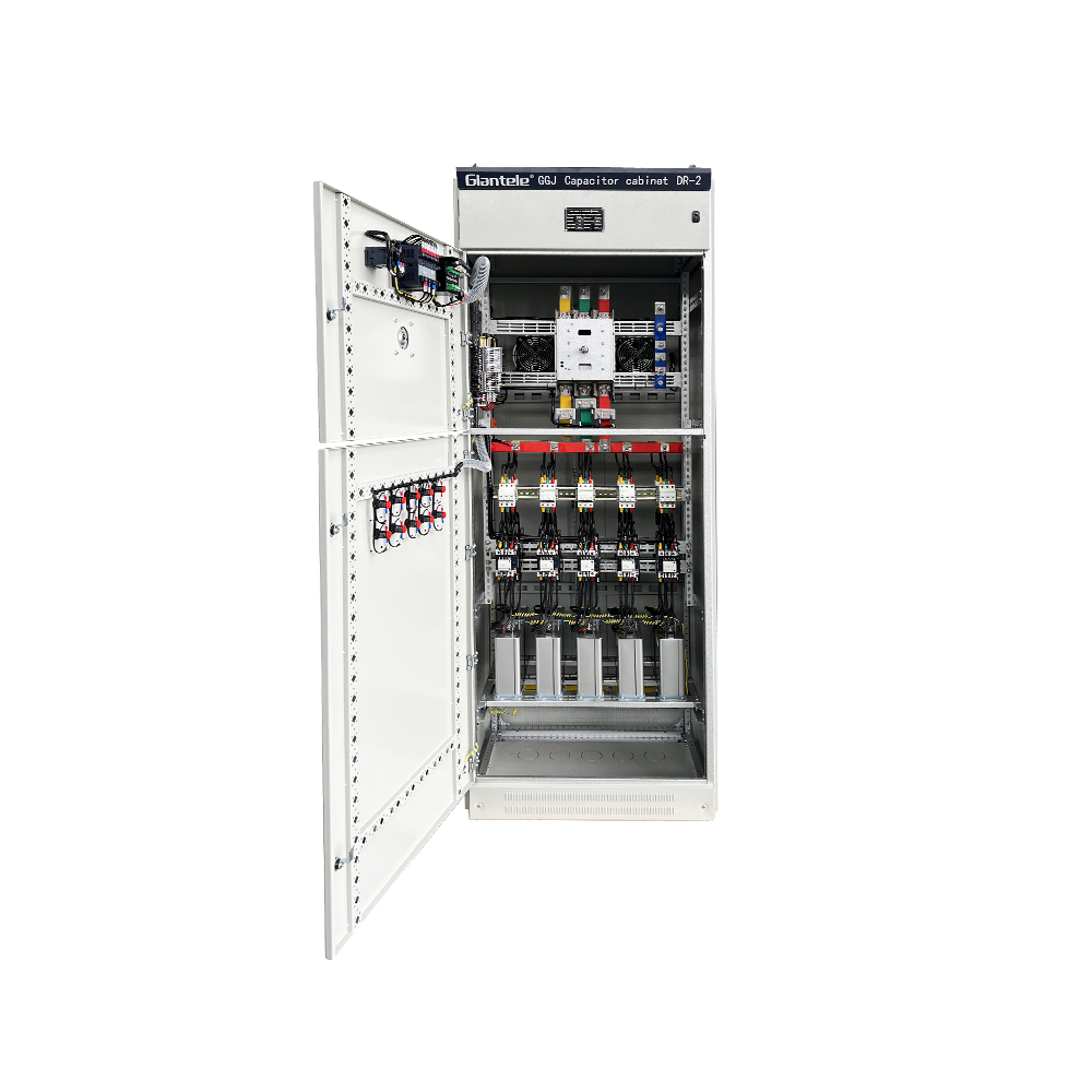


CE certified, IEC 60831 type-tested at an accredited laboratory. Every stage has its own HRC fuse link — one capacitor fault isolates only that stage. The rest of the bank keeps running. Mechanical door interlock prevents access to live busbar. Built-in discharge resistors meet IEC 60831 safety requirements. We configure regional compliance — SASO, SNI, GOST — for your destination market.
Standard range is 380V to 690V, 50kVAR to 1000kVAR. Step sizes are typically 25kVAR or 50kVAR. We build custom ratings for 220V systems and special high-ambient-temperature sites. Every capacitor stage uses polypropylene film dielectric with built-in discharge resistor — drains to below 50V in under 60 seconds after disconnection.
What is APFC panel sizing? It is the process of matching total kVAR and step sizes to your load profile — too few steps and you under-correct at low load, too many and the contactors cycle unnecessarily. A good apfc panel manufacturer builds each stage with its own fuse and contactor, uses polypropylene film capacitors with discharge resistors, and type-tests the complete bank to IEC 60831. Zhegui has been doing exactly this since 2013.
An APFC panel is an automatic capacitor bank — the controller reads voltage and current 50 times per second and switches capacitor stages as the load changes, preventing both under-correction and over-correction. A good apfc panel supplier provides IEC 60831 test reports for every stage, uses HRC fuse links per stage, and offers controller programming support. If the supplier hesitates on test reports, find another one.
Start with your 12-month utility bills. Average PF and peak kVA demand determine the kVAR correction you need. A 500kVA plant at 0.75 PF needs roughly 200kVAR to reach 0.95. Our capacitor bank for power factor correction spans 50kVAR to 1000kVAR in 25kVAR or 50kVAR steps. Send us your bills and single-line diagram for a free sizing calculation with payback estimate.
Your utility charges a penalty when power factor drops below 0.90 or 0.95 depending on your contract. A power factor capacitor bank corrects the lag, moving your PF back above the penalty threshold. We have seen facilities save 10 to 25 percent on monthly bills. Capacitor banks for power factor correction are the most cost-effective way to fix this — cheaper than SVG panels or synchronous condensers for most sites.
An LV capacitor bank is a set of polypropylene film capacitors installed at your main distribution board to inject leading reactive current. When motors, transformers, and inductive loads draw lagging current, a pfc capacitor bank cancels that lag and brings your power factor closer to 1.00. The utility meter stops charging you for reactive power, and your bill drops immediately.


Your utility bill has a line item you might be overpaying — the reactive power penalty. Most commercial and industrial tariffs charge you when power factor drops below 0.90, sometimes below 0.95. If your facility runs motors, chillers, pumps, or welding equipment, your power factor is probably somewhere between 0.70 and 0.85. That means 15 to 30 percent of every kVA you buy goes to waste. A power factor correction system fixes this. And the simplest, cheapest way to correct power factor is a capacitor bank.
Inductive loads — motors, transformers, fluorescent ballasts — draw current that lags behind voltage. That lagging current does zero useful work but still heats up your cables and transformers. Your utility meter sees it and charges you for it. A capacitor bank injects leading reactive current right at your main distribution board, canceling the lag. Your meter sees a power factor closer to 1.00, and your penalty disappears.
Nothing dramatic happens. No one notices. Your plant runs exactly as before. But your bill drops 10 to 25 percent every month from that point onward. That is why we call the capacitor bank the silent ROI — it works 24 hours a day, needs almost no maintenance, and pays for itself inside 12 to 18 months.
The core of every pfc capacitor bank is the capacitor element itself. We use metallized polypropylene film — a dielectric that self-heals when minor internal punctures occur. No liquid electrolyte, no drying out, no leakage. Rated for 130,000 hours at full load and rated temperature. That is roughly 15 years of continuous service.
Each capacitor also has a built-in discharge resistor. Disconnect the stage and it drains to below 50V in under 60 seconds — no external discharge circuit required. This meets IEC 60831 safety requirements. Maintenance crews can work on the bank without waiting around for capacitors to bleed down.
Capacitor bank sizing starts with your utility bill. Look at the average power factor over the last 12 months. Then look at your total kVA demand. The kVAR needed equals kVA times the difference between the tangent of your actual phase angle and the tangent of your target phase angle. Most engineers use tables for this, not calculators.
A factory pulling 500kVA at 0.75 PF needs roughly 200kVAR of correction to reach 0.95. A commercial building at 300kVA and 0.82 PF needs about 100kVAR. Our standard capacitor banks span 50kVAR to 1000kVAR in 25kVAR or 50kVAR steps. The controller switches stages in and out based on real-time PF, so you never over-correct.
A fixed capacitor bank works fine for a single motor or a steady 24/7 load — connect it and forget it. But most facilities have load that varies hour by hour. That is when an apfc panel earns its keep. The controller reads voltage and current 50 times per second, calculates the instantaneous power factor, and switches capacitor stages in or out as needed.
Below about 150kVAR, fixed banks often win on cost. Above 300kVAR with variable load, the automatic panel prevents both under-correction (you still pay penalties) and over-correction (leading PF can cause voltage rise and equipment stress). The controller also logs data — see your PF trend over weeks and months.
| Feature | Fixed Capacitor Bank | APFC Panel (Automatic) |
|---|---|---|
| Switching type | Manual / always on | Automatic, 50 readings/second |
| Best for | Steady single-motor load | Variable facility load |
| Over-correction risk | Possible at light load | Controller prevents it |
| Cost per kVAR | Lower | Higher, but pays back faster |
| Payback period | 12-18 months | 8-14 months with variable load |
The table tells the story. A fixed capacitor bank for power factor correction handles steady loads cheaply. The APFC panel handles real-world variable load and pays back faster. But before you commit, it helps to understand what is APFC panel actually doing that a fixed bank cannot — it reads your load 50 times per second and adjusts reactive current injection on the fly, preventing both under-correction penalties and over-correction voltage rise. For most multi-motor facilities, the automatic panel wins on total cost of ownership.
Capacitors fail eventually — the dielectric ages, a voltage transient hits, or harmonics overheat the element. When one capacitor fails, you do not want the entire bank to go offline. That is why we fuse every stage individually with HRC fuse links. The faulted stage clears itself. The remaining stages keep supplying reactive current. Your maintenance team swaps the fuse and the capacitor cell during the next scheduled shutdown. No emergency call-out, no production loss.
Fuse holders mount on the front of each stage compartment. No need to open busbar chambers to replace a fuse. Standard industrial HRC fuses available from any electrical wholesaler — no proprietary parts.
IEC 60831 covers shunt power capacitors of the self-healing type for AC systems up to 1000V. It specifies dielectric tests, thermal stability, discharge resistor performance, and endurance at elevated voltage. A capacitor bank without IEC 60831 testing is a gamble — you do not know whether the capacitors will last 2 years or 15.
Every power quality guide will tell you the same thing: ask for the IEC test certificate. Our capacitor banks ship with the IEC 60831 type-test report. If a supplier hesitates to share it, walk away. The IEC published this standard for a reason. The IEEE equivalent (IEEE 18) covers similar ground for the North American market.
Most facilities see payback inside 18 months. The ones with the worst starting power factor and the most operating hours see the fastest return. A power factor capacitor bank at a three-shift factory with 0.72 PF might pay for itself in 8 months. The same bank in a single-shift warehouse at 0.88 PF takes 20 months. Either way, after payback, every month of penalty savings is pure profit.
Pull your last 12 electricity bills. Find the power factor penalty line item. Multiply by 12 to get your annual penalty cost. Now compare that number to the cost of a capacitor bank sized for your load. In most industrial facilities, the penalty alone exceeds the bank cost inside 18 months. That is before counting the release of transformer and cable capacity, which lets you add load without upgrading your electrical infrastructure.
You want an apfc panel supplier who provides IEC 60831 test reports without hesitation. An apfc panel manufacturer with real production capacity — 20,000 square meters, 200 people, shipping to 50-plus countries — means your order arrives on time and works as promised. Capacitor banks for power factor correction are a long-term investment. Pick the supplier who treats them that way.
Send us your bills and single-line diagram. We will run the numbers, size the capacitor bank for your exact load, and tell you the payback in months — with the math shown. Standard APFC panels and fixed capacitor banks ship in 4 to 6 weeks from a 20,000 square meter factory to your site in any of 50-plus countries.
