


Secondary distribution substations must keep local loads energized while allowing operators to isolate faults quickly and safely. A ring main unit places switching, protection, isolation, and earthing functions in a compact assembly, making it easier to sectionalize a medium-voltage loop without shutting down every downstream transformer. Yet reliability depends on more than choosing an RMU by voltage alone. The equipment must match the network topology, fault level, environmental conditions, protection philosophy, cable arrangement, and future automation requirements.
How a Ring Main Unit Limits the Impact of Network Faults
Many secondary distribution networks use a looped cable arrangement with a normally open point. Under normal conditions, each part of the loop is supplied from one direction, but an alternative path remains available. When a cable section develops a fault, operators can open the switches on both sides of the affected section and restore healthy sections from the opposite direction. The ring main unit creates the sectionalizing points needed to perform this isolation without disconnecting the entire local network.
This arrangement reduces the outage area rather than making the system completely interruption-free. Restoration may require manual switching unless motorized mechanisms, fault indicators, communication devices, and an approved automation scheme are installed. The speed of recovery also depends on fault location, protection coordination, access to the substation, and the condition of the alternate feeder. A ring main unit therefore supports continuity, but it cannot compensate for an overloaded backup route or an incorrectly coordinated protection system.
The operational benefit becomes particularly important where one medium-voltage loop supplies several distribution transformers. A fault near one transformer can be separated while unaffected transformers remain available or are returned to service through the healthy side of the ring. This limits customer disruption and gives maintenance personnel a clearly isolated work zone. It also allows utilities and industrial operators to divide a growing network into manageable sections instead of treating a long feeder as one fault zone.
How the Main Switching and Protection Modules Work Together
The two ring feeder ways normally provide the incoming and outgoing connections that continue the medium-voltage loop. These ways commonly use load-break switches or switch-disconnectors capable of carrying normal current and interrupting specified load currents. Their purpose is routine network switching and sectionalizing, not unrestricted interruption of every possible short-circuit current. EN IEC 62271-103 covers alternating-current switches and switch-disconnectors above 1 kV, while the wider metal-enclosed assembly is addressed by EN IEC 62271-200.
A transformer feeder requires a protection function in addition to routine switching. Depending on the transformer rating and protection study, the tee-off may use a switch-fuse combination or a circuit breaker controlled by a protection relay. Fuses offer a compact method for clearing suitable transformer faults, while a circuit breaker provides adjustable protection and easier coordination with upstream and downstream devices. The correct choice must be based on transformer inrush, fault current, fuse characteristics, relay settings, earthing arrangement, and the utility’s selectivity requirements.
Earthing switches provide a means of grounding isolated cable or circuit sections before authorized work begins. Mechanical and electrical interlocks should prevent unsafe sequences, such as closing an earthing switch onto an energized circuit or accessing a cable compartment before isolation. Clear position indication is equally important because operators must be able to confirm the state of the switching devices. EN IEC 62271-102 addresses disconnectors and earthing switches, including their ratings, position indication, mechanical interlocking, and testing requirements.
Modern assemblies may also include voltage presence indicators, current transformers, fault passage indicators, protective relays, motor operators, and communication interfaces. These components can shorten fault-location time and allow a control center to monitor or operate selected ways remotely. However, automation should not be specified as a collection of optional devices without a control philosophy. The purchaser must define communication protocols, auxiliary supply, cybersecurity responsibilities, alarm logic, remote-trip permissions, and the fallback procedure when communication is unavailable.
Choosing the Right Insulation Technology and Configuration
Insulation technology affects footprint, environmental performance, maintenance planning, service conditions, and end-of-life handling. Gas-insulated, air-insulated, and solid-insulated designs can all serve secondary substations, but they manage electrical clearances and environmental exposure differently. The decision should follow a project risk assessment rather than a simple preference for the smallest cabinet. Local regulations, utility specifications, technician capabilities, expected service life, and disposal requirements must also be considered.
A Gas Insulated Ring Main Unit can provide a compact arrangement because its live components and switching devices are enclosed in a sealed stainless-steel chamber. The 12 kV design is offered with fixed or expandable module combinations and rated-current options of 630 A or 1,250 A. Its available modules include load-switch, switch-fuse, vacuum-switch, and circuit-breaker functions, allowing the lineup to be matched to different feeder duties. Optional electric operation and remote-control functions can also support distribution automation.
An Air Insulated Ring Main Unit uses dry air or nitrogen instead of SF6 for the sealed insulation system. The product is rated at 12 kV, 50 Hz, and 630 A, with modular load-switch and circuit-breaker arrangements. Its design includes an IP67 sealed enclosure, digital relay protection, and optional current transformers for automation requirements. This approach can suit projects prioritizing SF6-free operation while retaining a modular metal-enclosed format.
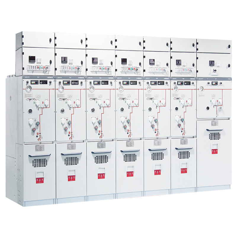
A Solid Insulated Ring Main Unit encapsulates live components in epoxy insulation rather than relying on SF6. The 12 kV, 630 A design supports combinations of circuit-breaker, load-switch, and switch-fuse functions. It also provides interlocking, visual isolation verification, directional pressure relief, and interfaces for remote control, measurement, and communication. Solid insulation may be attractive where sealed live parts and an SF6-free design are priorities, but thermal conditions, repair strategy, and end-of-life processing still require evaluation.
Insulation Approach | Practical Strengths | Questions to Resolve |
|---|---|---|
Gas insulated | Compact construction and sealed live parts | Gas handling, leakage procedures, regulations, and end-of-life recovery |
Air or dry-gas insulated | SF6-free design with familiar modular functions | Required footprint, pressure system, environmental limits, and inspection access |
Solid insulated | Encapsulated live parts and no insulating gas management | Heat dissipation, module replacement, material aging, and disposal process |
Regulatory direction can influence the lifecycle decision, especially for projects expected to remain in service for decades. Regulation (EU) 2024/573 introduced restrictions and servicing requirements affecting switchgear that contains fluorinated greenhouse gases. Projects outside the European Union may follow different schedules or permit different technologies, so the applicable local rules and utility policies should be checked during specification. Procurement teams should compare compliance over the equipment’s complete service life rather than only at the delivery date.
Ratings and Safety Details That Must Be Verified
Electrical Ratings Before Physical Size
Rated voltage is only the first line of the specification. Engineers must also verify system frequency, continuous current, short-time withstand current, peak withstand current, short-circuit making capacity, circuit-breaker interruption rating, and insulation withstand levels. Cable-charging and closed-loop switching duties may be relevant because ring feeders include significant cable capacitance and may be operated while energized. Each rating should exceed the calculated system duty under the approved network study, including foreseeable expansion.
The transformer way must be checked separately from the ring feeder ways. A 630 A busbar rating does not prove that the selected fuse or circuit breaker will protect a particular transformer correctly. Protection studies should confirm transformer inrush tolerance, overload protection, earth-fault sensitivity, fault-clearing time, and coordination with upstream devices. The ring main unit configuration should then be documented with a single-line diagram, module schedule, relay functions, instrument-transformer ratios, and approved settings.
Internal-Arc and Operator Protection
An internal fault can produce pressure, hot gases, molten material, and mechanical damage even when the primary protection clears correctly. The specification should define the required internal-arc classification, accessible sides, test current, test duration, room arrangement, and pressure-relief direction. A label stating that equipment is arc resistant is not enough unless its tested installation conditions match the proposed site. EN IEC 62271-200 includes classifications and test requirements for metal-enclosed assemblies, including internal-arc considerations and loss-of-service-continuity categories.
Interlocks, grounded metal partitions, cable-compartment access, operating handles, viewing windows, and voltage indication should be assessed as one operator-safety system. The pressure-relief path must not discharge toward an occupied aisle, escape route, adjacent low-voltage panel, or unprotected cable area. Operating procedures should identify which actions may be performed with the door closed and which require the circuit to be isolated and earthed. Site training must reflect the delivered configuration because operating sequences can differ between ring main unit designs.
Service Conditions and Future Expansion
Ambient temperature, altitude, humidity, condensation, salt contamination, dust, flooding exposure, seismic requirements, and indoor or outdoor installation can change the necessary enclosure and insulation design. Cable type, connector interface, termination height, bending radius, trench depth, and phase arrangement also affect whether a compact cabinet can actually be installed. The room must provide adequate access for cable work, operating handles, testing, replacement parts, and emergency escape. A technically suitable ring main unit can become difficult to maintain when the surrounding civil design ignores these requirements.
Future expansion should be defined before choosing fixed or extensible equipment. An extensible bus arrangement can simplify an additional feeder, but only when space, bus interfaces, protection capacity, and short-circuit ratings remain suitable. Spare ways may be justified where network growth is likely, although unused modules add cost and occupy space. The final decision should compare the expected expansion method with the practical disruption and risk of modifying an energized secondary substation later.
Installation, Commissioning, and Maintenance Practices
Installation quality directly affects the performance of the ring main unit. The foundation must be level, the lineup must be correctly aligned, and cable forces must not place excessive stress on bushings or connectors. Earthing conductors should follow the approved design, while cable screens and surge-protection arrangements must match the network earthing philosophy. Pressure-relief zones, ventilation openings, rear clearances, and access panels must remain unobstructed after nearby equipment is installed.
Commissioning should verify the delivered equipment against approved drawings before energization. Checks normally include nameplate data, module arrangement, mechanical operation, interlocks, earthing-switch function, cable connections, auxiliary wiring, instrument-transformer polarity, relay settings, alarms, and trip circuits. Functional tests should confirm local and remote commands, while protection testing should prove that the intended breaker opens through the complete trip chain. Test limits and methods must follow the manufacturer’s instructions, applicable EN IEC standards, and the project’s authorized commissioning procedure.
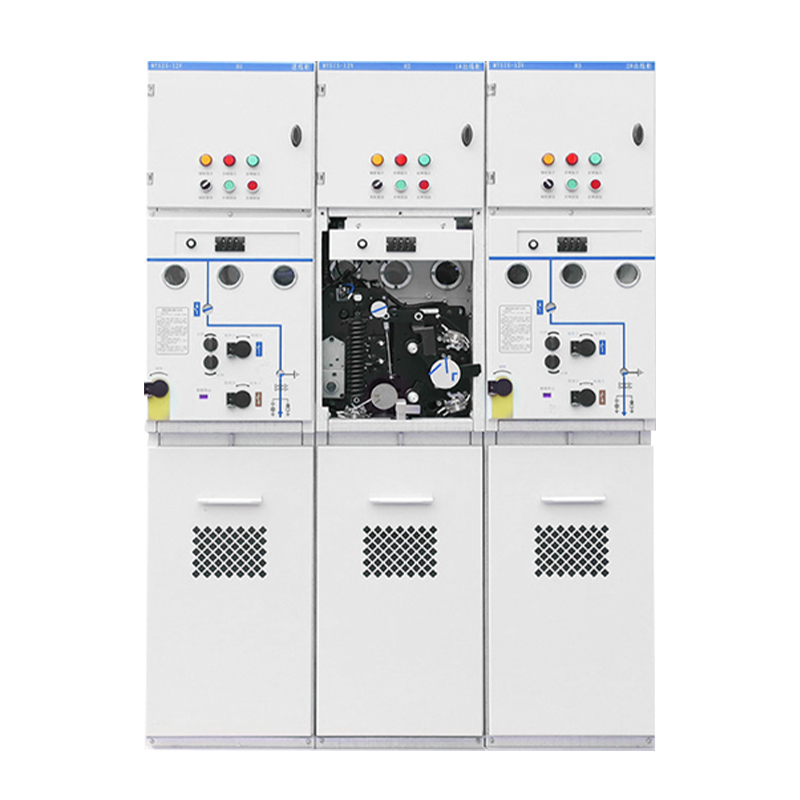
Maintenance planning should distinguish between sealed primary compartments and accessible operating, cable, protection, and auxiliary sections. A sealed chamber should not be opened merely because a calendar interval has passed; unauthorized opening can create hazards and invalidate the original sealing condition. Routine work may instead focus on cleanliness, corrosion, moisture, mechanism operation, indicators, heaters, auxiliary supplies, cable connections, relay records, and abnormal temperature or discharge signs. The actual intervals should reflect operating frequency, environment, fault history, manufacturer instructions, and utility practice.
Records are essential because gradual deterioration is difficult to recognize without a baseline. Operators should retain commissioning results, protection settings, operation counts, inspection findings, fault records, gas or pressure indications where applicable, and all configuration changes. Critical spares should be identified according to the installed mechanisms, relays, auxiliary components, and cable accessories. A ring main unit delivers its intended reliability only when trained personnel can interpret alarms, isolate equipment safely, and restore the network through a documented switching plan.
Conclusion
A ring main unit improves secondary-distribution resilience only when its topology, protection, insulation, and service conditions are matched as one system. Buyers should verify fault ratings, internal-arc strategy, cable interfaces, automation scope, and maintenance access before comparing footprint or price. Zhejiang Zhegui Electric Co., Ltd. is a manufacturer of low- and medium-voltage power distribution equipment, with gas-insulated, air-insulated, and solid-insulated RMU options for different project priorities. A disciplined specification and commissioning process delivers greater value than selecting equipment from nameplate voltage alone.
FAQ
Q: What does a ring main unit do in a secondary substation?
A: It connects and sectionalizes medium-voltage feeders, isolates faulty cable sections, protects transformer ways, and provides earthing points for safer maintenance and network restoration.
Q: Does an RMU guarantee an uninterrupted electricity supply?
A: No. It reduces the affected outage area and provides an alternative supply path, but restoration still depends on network capacity, protection coordination, switching speed, and automation.
Q: How should a ring main unit rating be selected?
A: Selection should consider voltage, continuous current, short-circuit withstand, making and breaking duties, insulation level, transformer protection, service conditions, cable interfaces, and future expansion.
Q: What is the difference between a load-break switch and a circuit breaker?
A: A load-break switch handles specified normal switching duties, while a circuit breaker interrupts fault current under protection-relay control and provides more adjustable transformer or feeder protection.
Q: Are SF6-free ring main units available?
A: Yes. Air or dry-gas insulated and solid-insulated designs avoid SF6, although footprint, thermal performance, maintenance strategy, environmental limits, regulations, and disposal still require project-specific comparison.
```