


A Ring Main Unit, commonly called an RMU, is compact medium-voltage switchgear that connects and controls feeder sections and transformer branches in an electrical distribution system. Its working principle is based on controlled switching: under normal conditions it maintains the intended feeder connections; during maintenance or a fault, it helps isolate the relevant section through the approved protection and switching sequence. In a ring network with an available alternate path, healthy loads may then be restored from the other direction. Understanding this principle helps engineers and buyers choose equipment for the network they actually operate.
Key Takeaways
The RMU working principle combines feeder connections, switching devices, protection, earthing, and interlocks in one medium-voltage assembly.
In a ring network, two feeder directions create the possibility of alternate supply, commonly managed around a normally open point.
A load break switch handles rated load switching within its duty; fault interruption requirements may call for fuses or a circuit breaker and protective relay.
Fault isolation and service restoration depend on the full system: network capacity, protection settings, cable condition, and operating procedures.
An SF6-free RMU or another technology choice must be evaluated against the specified electrical, environmental, and lifecycle requirements.
What Is a Ring Main Unit?
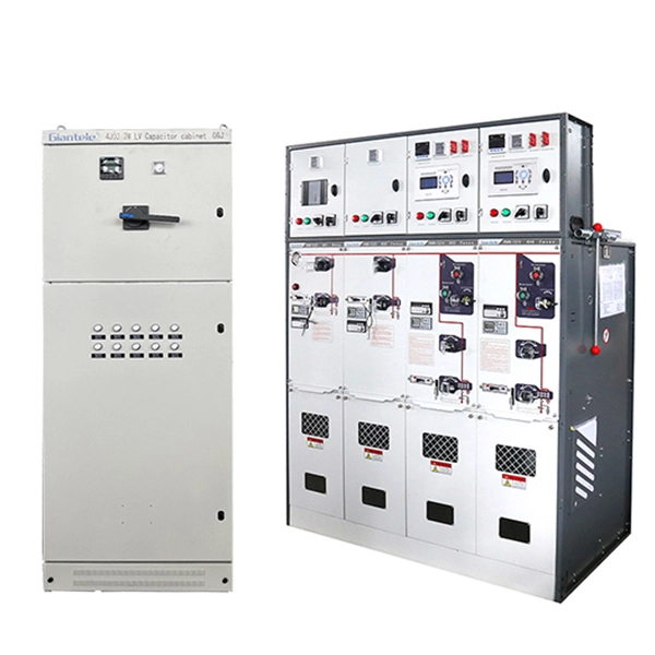
A Ring Main Unit is factory-assembled, metal-enclosed medium-voltage switchgear used at distribution nodes. It is often installed between feeder cable sections and a distribution transformer, or between multiple feeder sections in a compact substation, kiosk, industrial site, or commercial distribution room. The exact construction varies by manufacturer and configuration, but the functional goal is consistent: create manageable points where a medium-voltage circuit can be connected, switched, protected, isolated, and made safe for authorized work.
The name comes from its traditional use in a ring network. Instead of relying on one radial path to every downstream load, a ring arrangement connects distribution points around a route. A node may have one cable coming from the left and another leaving to the right, plus a transformer branch. When the ring is operated with a designated open point, power normally reaches different areas from defined directions. If a section becomes unavailable, switching can move the open point and use the healthy side of the ring when the design permits it.
The term is also used for compact switchgear in radial systems. In that case, the physical ring logic may not apply, but the RMU can still provide feeder switching, transformer protection, cable isolation, and a compact equipment boundary. Do not assume a product called an RMU automatically creates dual supply. The single-line diagram determines whether an alternate supply path actually exists.
For verified examples of product categories, see Giantele’s Ring Main Unit page. A product category is a starting point; the final configuration must follow the project’s electrical requirements.
The Ring-Network Concept Behind the Working Principle
Imagine several distribution transformers placed around a loop of medium-voltage cable. Each node has a switching device on each ring direction. Although the cable route is a loop, the system is commonly not run as a continuously closed electrical loop. Instead, one point is kept open under normal operation. This practice gives the network a clear normal power-flow arrangement and helps control the conditions considered in the protection design.
When a fault occurs in one cable segment, protective devices and operating personnel identify the affected portion. Switches at the boundaries of that portion are opened according to the approved procedure. The healthy parts of the network may then be energized from their respective available sides. The normally open point may be relocated if doing so restores supply without exceeding ratings or violating operating rules.
The core capacity check is plain text: remaining available source and cable capacity must be greater than or equal to the load supplied after the switching change. It should be supplemented by checks for voltage drop, motor starts, transformer loading, fault level, protection selectivity, and any critical-load restrictions. The RMU’s working principle gives the operator options; electrical studies decide which option is acceptable.
Main Parts and What Each Does
The components are designed to support a sequence of electrical operations rather than to operate independently. A common arrangement may include two ring ways and one transformer way, but configurations vary.
Component | Function in the RMU working principle | Important design consideration |
|---|---|---|
Ring feeder ways | Connect incoming and outgoing cable sections | Confirm number of ways, cable connectors, ratings, and future extensions. |
Load break switch | Makes or breaks load current within its assigned duty | Do not assume it provides the same fault interruption function as a circuit breaker. |
Circuit breaker or fuse-switch combination | Protects a feeder or transformer branch as specified | Coordinate selection with the protection study and transformer characteristics. |
Busbar system | Connects internal ways in the selected arrangement | Its ratings must suit normal and fault conditions. |
Earthing switch | Helps apply a controlled earth to the isolated circuit when procedures require it | Confirm interlocking and operating sequence. |
Cable compartment | Houses compatible termination interfaces | Allow for cable size, bending radius, screening, test access, and workmanship. |
Interlocks and indicators | Help guide safe operation and show equipment state | Review against the real site procedure, not only a brochure diagram. |
Monitoring or control equipment | Adds indication, sensing, communications, or motor operation | Specify data, power supply, communications, and authority to control. |
The load break switch performs a crucial but bounded job. It allows normal load current to be switched in accordance with its rating and operating duty. Fault clearing is generally handled by a protection device designed for that duty, such as a circuit breaker operating with appropriate protection or a correctly selected fuse-switch arrangement. Mixing those roles leads to weak protection assumptions. Always identify which device detects and clears which fault condition.
RMU Working Principle During Normal Operation
Under normal conditions, the RMU follows the state defined by the network operating plan. In a simple 2+1 node, the two ring cable ways may establish the feeder continuity around the node, while the transformer branch is connected through its dedicated protection arrangement. The operating position depends on the system’s open point and supply direction; there is no universally correct handle position without the approved single-line diagram.
Current enters through an energized feeder path, passes through the selected internal bus and switching devices, and leaves toward the next cable section or transformer branch. Protection equipment supervises the conditions it is designed to detect. Position indicators and, where provided, remote status points communicate the equipment state. The unit remains compact because these functions are integrated, but compactness does not reduce the importance of correct cable terminations, insulation coordination, access, and earthing practice.
For a transformer branch, normal operation means the branch protection device is closed and the transformer is supplied within its intended operating range. The RMU does not regulate the transformer’s voltage transformation itself. Its role is to provide the upstream medium-voltage connection and a defined means of disconnection and protection.
What Happens When a Fault Occurs
The fault response begins with the protection philosophy, not with a manual switching action. Depending on the location and equipment, a fuse, relay-controlled circuit breaker, or upstream protective device may operate. Fault passage indication or monitoring may assist location, but indication is not a substitute for confirmation and approved operational decision-making.
Once the affected section is identified, authorized operators use the RMU switching points to isolate it from every possible source. In a ring cable fault, this often means opening the switches at both ends of the damaged segment. If the remaining healthy feeder sections have a viable supply path, operators may close the appropriate connection from the alternate side and establish a new normal open point. The faulted cable remains isolated until it is tested, repaired, and returned through the approved process.
In a transformer fault, the dedicated transformer-protection way may disconnect the branch while ring feeders remain available. In a feeder fault, the relevant feeder protection and adjacent sectionalizing points determine the extent of isolation. The desired outcome is selective operation: remove the smallest practical section while keeping the protection system dependable. Achieving that outcome requires coordination studies and commissioning verification before the system is placed in service.
Maintenance and Earthing: The Safety Principle
The RMU working principle also includes how equipment is made safe for maintenance. Switching off one device is not automatically sufficient. A safe work process normally requires a documented isolation from all sources, verification steps under the site’s rules, application of earths where required, locks or tags, and a clear handover to the work team. Backfeeds from alternative sources, generators, transformers, or connected equipment must be considered.
An earthing switch and mechanical interlocks can support this process by enforcing or guiding the sequence. For example, a design may prevent cable-compartment access until the associated circuit is in the correct isolated and earthed state. Details differ between equipment designs, so personnel must follow the manufacturer documentation and the owner’s procedure. Never infer a safe operation sequence from a general description of an RMU.
The maintenance strategy should also address inspection, cleaning where appropriate, operating-mechanism checks, protection testing, cable testing, indication verification, and communications checks for smart equipment. The interval and scope depend on the technology, service conditions, site policy, applicable standard, and manufacturer guidance. Sealed or low-maintenance equipment still requires a disciplined lifecycle plan.
Ring Main Unit Technology Choices
RMUs may use gas insulation, solid insulation, air insulation, or other design approaches. The correct choice is not determined by a single claim such as “maintenance-free” or “eco-friendly.” It should be evaluated against the required voltage class, insulation and interruption design, footprint, ambient conditions, corrosion exposure, lifecycle support, environmental strategy, monitoring needs, and local regulations.
SF6-free RMU options can be relevant to projects seeking to reduce reliance on SF6 while retaining the operational functions required at the distribution node. The term alone does not establish suitability. Compare verified technical data, applicable standards, ratings, enclosure requirements, maintenance instructions, and project-specific environmental constraints. Giantele presents SF6-free Ring Main Unit equipment within its product offering; the final selection should be confirmed against the client’s specification and approved engineering design.
Technology choice also influences installation. Outdoor applications may face sun, rain, condensation, salt, dust, or flooding risk. Indoor applications may be constrained by room size, access, fire strategy, ventilation, and cable routes. A compact cabinet does not remove these questions; it makes it even more important to verify the complete installed arrangement.
Smart RMUs and Distribution Automation
An intelligent RMU can add motorized switches, fault indicators, sensors, protective relays, communications, and remote-control capability. These features extend the working principle from local manual switching to monitored or remotely assisted operation. The potential benefit is quicker information flow, more consistent event records, and, in a well-designed system, faster restoration actions.
The boundary is important: remote control must never bypass the protection and operating philosophy. A smart configuration needs clear answers on command authority, local/remote selection, interlock status, communications protocols, auxiliary supply, loss-of-communications behavior, time synchronization if records are used, and cybersecurity controls. Site teams also need a local fallback procedure. Automation is most valuable when it reduces uncertainty and delay without making the safety process opaque.
For projects that need a wider array of feeder and protection arrangements, review Giantele’s medium-voltage switchgear portfolio. An RMU is powerful within its intended scope, while a larger MV switchgear arrangement may suit more complex protection, metering, or incomer requirements.
How to Select an RMU for the Actual Network
Begin with a complete single-line diagram and normal operating state. Define the source points, feeder directions, normally open point, transformer branches, load priorities, and expected contingencies. Then identify rated voltage, rated current, insulation level, short-circuit withstand and making duties, required protection functions, cable interfaces, enclosure conditions, and standards. This produces a defensible technical basis for comparing configurations.
Next, walk through operation scenarios: cable fault, transformer fault, scheduled cable work, loss of a feeder, loss of auxiliary supply, and loss of remote communications. For each case, identify the intended device operations, the isolation boundary, the loads that remain supplied, and the loads that must be shed. If that sequence cannot be explained clearly, the configuration or operating plan needs further work.
Finally, consider the people who will commission and maintain the installation. Request operating documentation, wiring diagrams, interlock descriptions, test requirements, spare parts guidance, and training. Zhejiang Zhegui Electric Co., Ltd. can discuss a configured Ring Main Unit solution when the project data is available. Engineering approval and compliance with the local system owner’s requirements remain essential.
Conclusion
The Ring Main Unit working principle is simple at its core: connect the required feeder paths in normal service, use coordinated protection to respond to abnormal conditions, and use controlled switching and earthing to isolate a section safely when work or fault recovery requires it. In a properly designed ring network, those functions make alternate supply routes practical for healthy loads.
The detail is where successful projects are won. A reliable RMU installation depends on correct ratings, protection coordination, cable design, interlocks, operator procedures, environmental suitability, and a realistic restoration plan. Specify the unit as part of the network—not as an isolated cabinet—and its switching principle can support safer, more resilient medium-voltage power distribution.
FAQs
What does RMU stand for in electrical distribution?
RMU stands for Ring Main Unit. It refers to compact medium-voltage switchgear commonly used for feeder switching, protection, and isolation in ring or radial distribution systems.
How does an RMU restore power after a cable fault?
After the faulted cable section is identified and isolated from all relevant sources, authorized operators may restore healthy sections from an alternate feeder direction if the network topology, capacity, protection settings, and operating rules permit it.
Is a load break switch the same as a circuit breaker?
No. A load break switch is designed for rated load switching within its duty. A circuit breaker, normally used with a protection relay, has a different protection and fault-interruption role. The selected devices must match the system protection design.
Why is a ring network normally operated with an open point?
The normal open point establishes the intended supply arrangement and helps the network operate according to its designed protection and power-flow conditions. Its location can be changed during an approved restoration sequence.
What is an SF6-free RMU?
It is an RMU that uses a design intended to avoid SF6 insulation gas. Suitability must still be assessed against the application’s electrical ratings, installation conditions, maintenance plan, environmental objectives, and specification.
Can a Ring Main Unit be used in a radial network?
Yes. Even without a true alternate ring supply, it can provide a compact feeder or transformer switching, protection, and isolation point. The resilience outcome will depend on the available network paths.