


Motor Control Center separation shapes how you access an MCC and its internal parts during maintenance.
Choose Form 2, Form 3, or Form 4 by checking which parts need separation.
This guide explains the differences and helps you prepare a clear purchase specification.
What Does Internal Separation Mean?
Internal separation divides parts inside a low-voltage assembly. Engineers also call this internal segregation, and both terms describe the same basic concept.
The layout matters because technicians need clear boundaries between equipment, power paths, and cable connections. However, a form number describes construction rather than permission to work on live equipment.
Three parts help explain the differences:
Busbars: These conductors distribute power within the assembly. Drawings may also describe them as bus bars.
Functional units: These contain equipment serving a particular circuit, such as a motor starter and its protection devices.
Cable terminals: These connect external cables to the assembly. Specifications may call them cable connection terminals.
A functional unit can include several devices working together. Therefore, separating units means more than placing contactors beside each other.
For European projects, EN IEC 61439-1 provides general assembly requirements. EN IEC 61439-2 addresses power switchgear and controlgear assemblies, including forms of internal separation.
For low-voltage switchgear, review the complete assembly rather than individual devices.
Your LV switchgear specification should connect access requirements with verified ratings.
Use the form designation together with drawings and verified assembly ratings. A short product description cannot show every access boundary.
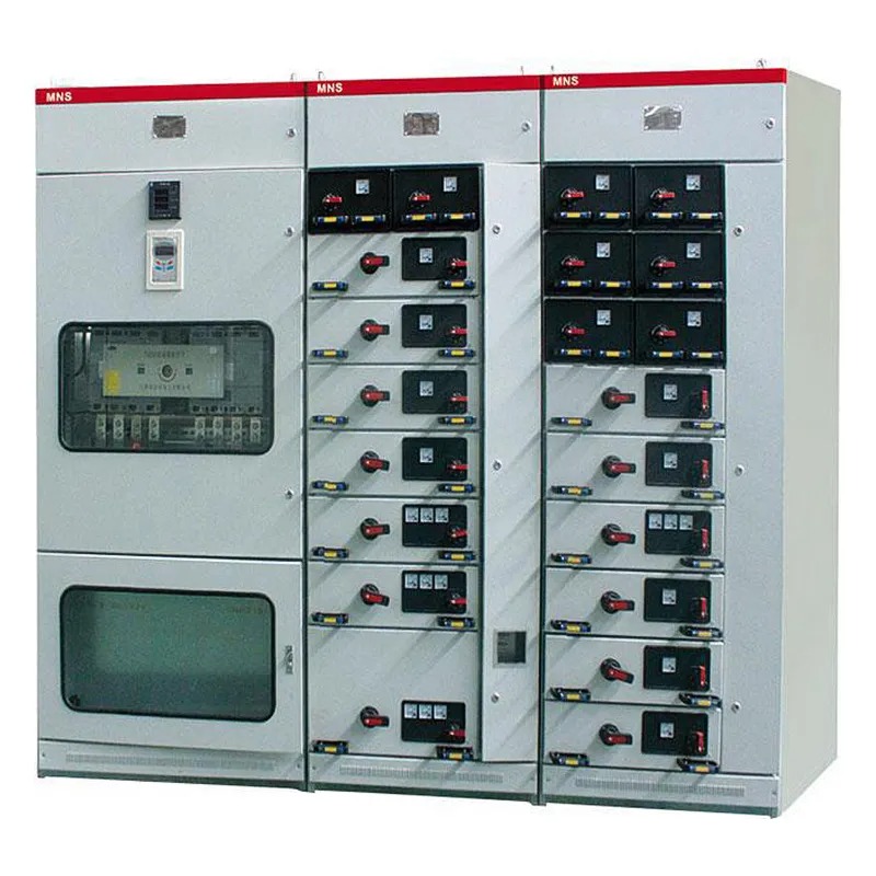
Form 2, Form 3, and Form 4 Explained
The main difference concerns how far separation extends through the assembly. The letter suffix adds important detail, so always include it in your specification.
Form 2a: Busbars Separate from Functional Units
Form 2 separates busbars from functional units. However, it does not require separation between the functional units themselves.
In Form 2a, terminals for external conductors do not have separation from the busbars. This distinction matters when reviewing cable connection access.
Consider this arrangement when your maintenance plan permits suitable shutdowns. Ask the supplier to show what becomes accessible after removing each cover.
Avoid assuming that one starter has its own protected workspace. The form alone does not establish that boundary between adjacent units.
Form 2b: Add Terminal Separation from Busbars
Form 2b keeps external conductor terminals separate from the busbars. However, the functional units still do not require separation from each other.
This arrangement changes the boundary around cable connections compared with Form 2a. It does not provide the individual unit separation found in Form 3.
Review the terminal layout before deciding whether it matches your maintenance tasks. A shared equipment area may still affect how technicians reach individual circuits.
Form 3a: Separate the Functional Units
Form 3 adds separation between functional units. Therefore, each unit has separation from neighbouring units, as well as the busbars.
In Form 3a, terminals for external conductors do not have separation from the busbars. The terminal arrangement remains an important limit during access planning.
This form can support projects that need clearer boundaries between motor circuits. Still, assess the connection area separately from the equipment area.
Ask where technicians stand, which covers they remove, and what remains behind those covers. These questions turn a form designation into a practical access review.
Form 3b: Separate Terminals from Busbars
Form 3b separates busbars from functional units and separates those units from each other. External conductor terminals also have separation from the busbars.
Form 3 separates external conductor terminals from functional units, but not necessarily from other circuits' terminals. Therefore, a shared terminal area can remain.
This distinction often decides whether Form 3b meets the project requirement. Individual starter compartments do not automatically mean individual terminal compartments.
Review both equipment access and cable work. The assembly should match your intended tasks, rather than only the appearance of its front doors.
Form 4a: Keep Associated Terminals with Their Unit
Form 4 adds separation between the terminals associated with different functional units. Those terminals also have separation from the busbars.
In Form 4a, the terminals share a compartment with their associated functional unit. They remain separate from other units and their terminals.
This layout keeps the circuit equipment and its external connections together. Check whether that arrangement fits your inspection and replacement process.
Ask the supplier to identify all relevant connections on the compartment drawing. Do not judge the arrangement solely from the number of visible doors.
Form 4b: Give Associated Terminals a Separate Compartment
Form 4b places external conductor terminals outside their associated functional unit's compartment. The required separation from other units' terminals also remains.
This arrangement gives cable connections a separate compartment boundary. However, access conditions still depend on the complete design and operating procedure.
Specify the intended task clearly, whether technicians need equipment access or connection access. Then check the actual barriers and cable routes.
Form 4b does not automatically mean withdrawable construction. Withdrawal features and internal segregation describe different aspects of the assembly.
Arrangement | Busbars separate from units | Units separate from each other | External terminal arrangement |
|---|---|---|---|
Form 2a | Yes | Not required | Not separate from busbars |
Form 2b | Yes | Not required | Separate from busbars |
Form 3a | Yes | Yes | Separate from units; not separate from busbars |
Form 3b | Yes | Yes | Separate from units and busbars; circuits may share terminal space |
Form 4a | Yes | Yes | Separate by unit; within associated unit compartment |
Form 4b | Yes | Yes | Separate by unit; outside associated unit compartment |
Choose Separation Around Your Maintenance Tasks
Start with the work your team expects to perform. A higher form number may add useful boundaries, but the right choice follows your access needs.
First, list the tasks that require opening the assembly. Separate visual checks, starter replacement, cable inspection, and future circuit additions.
Next, decide which shutdowns your process can accept. Consider the motor under maintenance and any neighbouring equipment that shares the same supply.
Then review the arrangement with these questions:
Can the process stop during planned electrical maintenance?
Which functional units need independent access boundaries?
Do technicians need access to individual cable terminals?
Could shared connection space restrict the planned work?
Which circuits must remain available during the shutdown?
For example, a workshop that accepts full shutdowns may consider Form 2. A process with many independent motor circuits may need the unit separation of Form 3.
If separate circuit connections form a key requirement, review Form 4. Choose between Form 4a and Form 4b after checking the intended connection access.
These examples guide discussion rather than prescribe a form for an entire industry. Two pumping stations can have very different maintenance and supply arrangements.
Tip: Describe the maintenance task before requesting a form number, and ask the supplier to demonstrate the matching boundaries.
Check Access, Cable Space, and Heat Together
Good separation needs a practical layout around it. A compartment boundary helps little if the intended cable cannot reach its connection comfortably.
Give the supplier your cable sizes, cable quantities, and entry direction. Also explain whether installers need front access, rear access, or both.
Check the working space around cable connection terminals. Allow for cable bending, connection tools, identification labels, and the installation sequence.
Bus bars also need a layout that suits the assembly's current rating. However, the separation form does not establish its thermal performance.
Ask how the proposed configuration supports the required temperature-rise verification. The answer should cover the actual devices and arrangement in your project.
Drives and other heat-producing equipment deserve attention during layout review. Added partitions can affect available space and airflow, so evaluate the complete configuration.
Future expansion deserves the same level of detail. Reserve space alone does not establish a safe method for adding another circuit.
Ask where new cables will pass and how installers will reach the spare position. Review whether future changes would alter the original separation boundaries.
What a Form Number Does Not Prove
Internal separation can help reduce accidental contact and the chance of certain internal faults. However, it does not establish every aspect of electrical safety.
Keep these separate questions in your technical review:
Requirement | What to request |
|---|---|
Internal separation | Exact form and compartment drawings |
Temperature rise | Verification covering the proposed assembly configuration |
Short-circuit performance | Relevant ratings and supporting verification |
Internal arc performance | Separate evidence and stated conditions, when required |
Withdrawable construction | Defined positions, interlocks, and operating instructions |
Maintenance access | Task-specific isolation and access arrangements |
A Form 4 Motor Control Center does not automatically contain an internal arc. Separate evidence must address any claimed arc performance and its conditions.
Similarly, an MCC with drawers still needs a clear separation specification. Drawers describe equipment movement, while forms describe internal boundaries.
Qualified personnel must plan isolation and verify safe conditions before maintenance. Adjacent circuits remaining energised require careful assessment and suitable protective measures.
CE marking also serves a different purpose from a separation designation. It concerns conformity with applicable EU legislation, rather than selecting Form 2, 3, or 4.
For equipment within its scope, the Low Voltage Directive 2014/35/EU places conformity responsibilities on the manufacturer. It does not require notified-body involvement.
Therefore, review the EU declaration of conformity alongside the technical documentation. A certificate logo alone cannot establish the specified assembly arrangement.
Prepare a Clear Specification for Giantele
Send a project brief that connects your operating needs with the required layout. This makes supplier discussions more useful and helps compare proposals fairly.
Include the following information in your enquiry:
Supply voltage, frequency, and required assembly current rating.
Motor quantities, power ratings, and intended starting methods.
Required short-circuit ratings and relevant project conditions.
Exact separation form, including its letter suffix.
Cable sizes, entry direction, and available installation space.
Planned maintenance tasks and acceptable shutdown arrangements.
Ambient conditions, installation location, and future circuit requirements.
For a preliminary Form 4b request, describe why separate terminal access matters. Then ask for drawings showing each unit and its associated terminal compartment.
Request confirmation of the proposed EN IEC 61439-1 and EN IEC 61439-2 assessment basis. Also ask which documents cover your final configuration.
Compare suppliers against the same task list and technical requirements. Otherwise, two quotations may use similar labels but offer different access arrangements.
Giantele supplies low- and medium-voltage power distribution equipment and offers technical support. Share your motor schedule and access requirements to start the design discussion.
Conclusion
Choose Form 2 for busbar separation, Form 3 for unit separation, and Form 4 for individual circuit terminal separation.
Then check the suffix, access drawings, and verified ratings against your actual maintenance tasks.
Contact Giantele with your Motor Control Center requirements and request a layout suited to your project.
FAQ
Q: Which Motor Control Center separation form should I choose?
A: Choose your Motor Control Center form around maintenance access and shutdown needs. Review busbar, unit, and terminal boundaries before approving the layout.
Q: Does a Form 4 Motor Control Center permit live maintenance?
A: A Form 4 Motor Control Center does not grant permission for live maintenance. Qualified personnel must assess each task and establish suitable isolation and protection.
Q: Does a withdrawable MCC always provide Form 4b separation?
A: Withdrawable construction does not automatically establish Form 4b separation. Request the MCC compartment drawing and a clear statement of the proposed form.
Q: What distinguishes Form 4a from Form 4b internal segregation?
A: Both arrangements separate different units' external conductor terminals. Form 4a keeps associated terminals with their unit, while Form 4b uses a separate compartment.