


Motor Control Center cable entry affects installation space, cable routing, and future MCC maintenance. Top and bottom connections can both work, but the right choice depends on the complete cable route. Start with the room layout, then check the space inside the assembly.
Cable Entry and Terminal Position Are Different
Cable entry describes where cables pass through the enclosure. Terminal position describes where those cables connect inside it.
A cable entering from above may still travel down a vertical cable compartment. Similarly, bottom entry does not guarantee that every connection sits near the floor.
Ask for a section drawing that shows the complete path. Include the incoming supply and outgoing motor circuits, because they may use different arrangements.
Power cables and control wiring also need suitable routes. A single entry direction does not mean every cable should share the same space.
Top entry, also called upper cable entry, often suits overhead cable routes. Bottom entry, or lower cable entry, often suits floor trenches and raised bases.
Neither choice establishes a universal safety advantage. The enclosure design, installation conditions, and access arrangements determine whether the finished solution works.
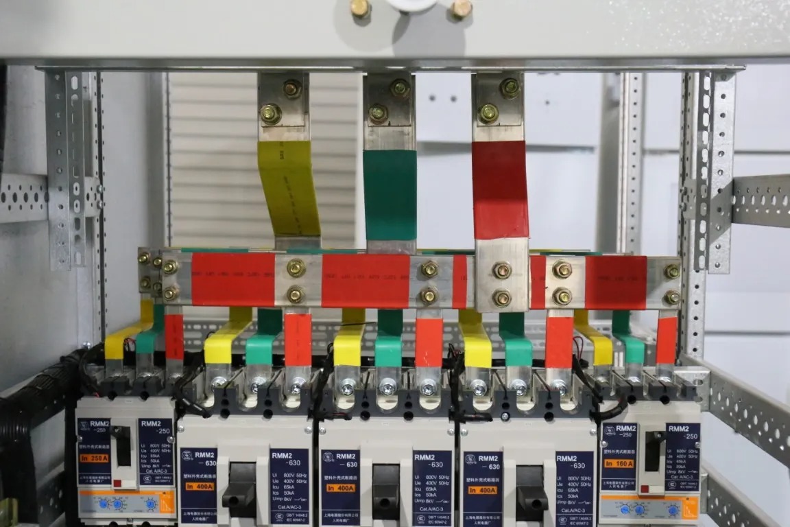
Six Checks Before Choosing Top or Bottom Entry
Follow the External Cable Route
Draw the route from the building cable tray to the enclosure. Then continue the line through the cabinet to the intended connection.
Overhead trays may favour top entry because cables can approach from above. Floor trenches may favour bottom entry because the route already approaches from below.
However, check the actual tray position rather than its general direction. A tray behind the panel may require a different bend than one directly above it.
Allow Space for Cable Bending
Cable makers specify minimum bend radii for their products. Use those values with the cable diameter and installation method.
Check the bend at the enclosure entrance and again near the connection. A cable may pass through the opening but still lack enough internal turning space.
Large cables and parallel runs need particular attention. Ask for a layout that shows realistic cable envelopes rather than thin schematic lines.
Confirm Installation and Maintenance Access
Entry direction and access direction describe separate decisions. Top-fed cables may terminate in a front-access or rear-access compartment.
Check whether installers can reach the connections with the panel in its final position. A drawing that assumes rear access will fail beside a permanent wall.
Also consider future replacement of one cable. The team should understand which covers and neighbouring cables could obstruct that task.
Review Cable Support and Mechanical Load
Heavy cables need suitable support along their route. Terminal connections should not carry cable weight or pulling forces beyond their design limits.
For top entry, review how the overhead route supports descending cables. For bottom entry, check how cables rise from the trench into the compartment.
Specify support positions with the supplier and installer. Avoid leaving this decision until the cables already occupy the available space.
Match the Entry to the Environment
Water, dust, and pests can enter through poorly finished openings. Review the cable gland system, entry plate, and unused-hole closures together.
Top entry needs attention where overhead leaks or washing could affect the enclosure. Bottom entry needs attention where trenches collect water or debris.
Neither arrangement makes a cabinet floodproof. Address the room conditions and enclosure requirements rather than relying on entry direction alone.
Reserve a Practical Expansion Route
Spare circuit space does not automatically provide spare cable space. Future cables still need suitable openings, support, and access to their connections.
Mark the proposed expansion route on the layout drawing. Check whether installers could add cables without disturbing unrelated circuits.
For mixed top and bottom routes, identify each circuit group clearly. Otherwise, future additions may cross paths that originally remained separate.
Project condition | Top entry consideration | Bottom entry consideration |
|---|---|---|
Overhead cable tray | Direct approach may simplify routing | Additional route downwards may be needed |
Floor trench | Cables need a route upwards first | Direct approach may suit the existing route |
Limited ceiling clearance | Check external cable bending space | Check internal rise and bending space |
Wet or dirty trench | Avoid exposure along any shared route | Review trench conditions and sealing closely |
Future circuit additions | Reserve overhead and internal access | Reserve trench and internal access |
Coordinate the Cable Compartment Layout
A cable compartment, also called a cable chamber, must suit the actual cable schedule. Count cables by circuit, size, and number of parallel runs.
Ask the supplier to mark cable terminals on the drawing. These cable connection terminals need sufficient access for the selected lugs and installation tools.
Check how incoming and outgoing routes interact. A large supply cable should not block access to smaller motor connections.
Control and communication cables also need a planned route. Follow the device instructions for separation, screening, and connection methods where these apply.
The layout should preserve the specified internal separation. Entry openings must not create an uncontrolled path through required barriers.
For European assembly specifications, discuss EN IEC 61439-1 and EN IEC 61439-2 with the manufacturer. Request verification appropriate to the final configuration.
Changing an entry plate or cable route may affect the original arrangement. Obtain supplier approval before changing the completed assembly.
Specify Entry Plates, Glands, and Cable Data
A gland plate is more than an empty sheet with holes. Its material, opening pattern, seals, and support details must match the cable installation.
Give the manufacturer a complete cable schedule:
Circuit names and cable identification references.
Conductor material, cable construction, and overall diameters.
Number of cables per circuit and entry direction.
Required cable gland type and environmental conditions.
Lug dimensions and the proposed connection arrangement.
Spare circuits and the expected expansion route.
For single-core AC cables, ask the designer to assess heating around metallic entry arrangements. Do not assume any steel plate suits every conductor layout.
Have the supplier specify the approved arrangement rather than improvising cuts on site. Preserve the enclosure's required mechanical strength and protection.
During installation, remove designated plates before drilling, following the assembly instructions. Keep metal debris away from electrical equipment and protect cable insulation from sharp edges.
Tip: Approve cable routes and connection details before approving the cabinet dimensions, because late cable changes can require layout changes.
Review a Realistic Site Scenario
Consider a plant with an overhead tray and limited floor access. Top entry offers a logical starting point for its cable route.
However, the tray sits close to the ceiling. The engineer must check whether cables can turn into the cabinet without exceeding their bending limits.
Now consider a second room with a dry cable trench beneath the lineup. Bottom entry may provide a more direct route for its motor circuits.
Yet a shallow trench can still create difficult bends. The team may need a different base arrangement or a revised trench design.
These comparisons show why entry direction alone cannot settle the decision. Review the full route before choosing the enclosure arrangement.
A useful review meeting compares three drawings together:
The room plan identifies trays, trenches, doors, and maintenance access.
The enclosure section shows entries, barriers, and internal cable routes.
The connection detail shows lugs, terminals, and required working space.
Resolve clashes between those drawings before manufacturing starts. This approach helps prevent installation changes that compromise the approved design.
Prepare Your Giantele Enquiry
Send the room layout and cable schedule with your Motor Control Center enquiry. State whether the project needs top, bottom, or mixed entry.
Include any restrictions on rear access, ceiling clearance, or trench depth. Also describe future circuit additions and the proposed installation sequence.
Giantele supplies low- and medium-voltage distribution equipment and offers technical support. Ask its team to review the proposed cable route against your project requirements.
Request a marked drawing rather than a simple confirmation of entry direction. The drawing should identify cable chamber access and the final connection positions.
For each MCC proposal, compare the same installation assumptions. A cabinet that appears compact may need additional external cable space at the site.
Confirm who supplies glands, supports, lugs, and sealing parts. Clear responsibilities help the installation team prepare the correct materials before delivery.
Conclusion
Choose cable entry around the complete route, including bends, support, sealing, and access to individual connections.
Top and bottom entry both need a cable layout that matches the installation site.
Send Giantele your Motor Control Center cable schedule and request a drawing for your preferred arrangement.
FAQ
Q: Is top cable entry better for a Motor Control Center?
A: Top entry can suit a Motor Control Center beneath overhead trays. However, check ceiling clearance, cable bends, support, and sealing before selecting it.
Q: Can a Motor Control Center use both entry directions?
A: A Motor Control Center can use mixed entry when its approved design supports the arrangement. Specify each cable route and verify access and internal separation.
Q: Does bottom entry require a cable trench?
A: Bottom entry can use a suitable trench, raised floor, or other designed approach. Confirm how the cables reach the cable compartment before choosing the base arrangement.
Q: Should upper cable entry determine the terminal location?
A: Upper cable entry does not determine the terminal location. Ask for a drawing showing the complete route to the cable terminals.