


Introduction
Unexpected motor trips, unstable speed, overheating, and recurring fault codes often begin with conditions outside the drive itself. Dust, restricted airflow, moisture, loose terminals, unsuitable parameters, and changing mechanical loads can gradually reduce VFD Panel reliability before a complete failure occurs.
Effective maintenance therefore involves more than cleaning the cabinet after a fault. A structured VFD Panel maintenance program combines safe isolation, operating-data reviews, environmental control, electrical inspections, and disciplined troubleshooting. The following guidance explains what to inspect, how to recognize common problems, and how to prevent small abnormalities from becoming costly shutdowns.
Prepare the VFD Panel Before Inspection or Maintenance
Only qualified electrical personnel should open, inspect, test, or repair industrial control equipment. Before internal maintenance begins, stop the connected process correctly, isolate all incoming and auxiliary power sources, apply the facility’s approved energy-control procedure, and verify that the equipment is de-energized with suitable test instruments.
Stopping the motor from the keypad does not make a VFD Panel electrically safe. Internal capacitors can retain hazardous energy after the incoming supply has been disconnected. External control circuits, bypass arrangements, shared control power, and rotating permanent-magnet motors may also introduce voltage into parts of the system.
Technicians should follow the discharge time and verification procedure specified for the installed drive. They should never assume that a blank display or extinguished indicator confirms a safe condition. Covers, barriers, and guards should remain in place until the approved maintenance procedure requires their removal. Official drive hardware documentation also emphasizes verifying the absence of voltage before maintenance begins.
Before changing wiring or parameters, record the condition that led to the inspection. Useful information includes:
The complete fault or warning code
The time and operating stage when the fault appeared
Input voltage and phase condition
Output current and commanded frequency
Motor speed and process load
Cabinet and ambient temperature
Recent parameter or equipment changes
Unusual noise, odor, vibration, or visible damage
Photographs of terminal positions and internal conditions can help preserve evidence before components are disturbed. An approved parameter backup is equally valuable because it provides a reference if settings have been changed during troubleshooting.
A modular VFD Control Panel can provide organized access to motor-control, protection, communication, and cooling components. However, maintenance decisions must still be based on the installed drawings, equipment documentation, application conditions, and actual panel configuration.

Build a VFD Panel Maintenance Schedule Around Operating Conditions
A fixed annual inspection is not sufficient for every installation. The appropriate VFD Panel maintenance frequency depends on dust levels, humidity, ambient temperature, operating hours, process criticality, loading, vibration, and the consequences of an unexpected shutdown.
A panel in a clean electrical room may require less frequent cleaning than one installed near cement dust, textile fibers, oil mist, material handling equipment, or high-moisture processes. Maintenance intervals should be shortened whenever filters become blocked quickly, cabinet temperature trends upward, or the drive operates close to its rated load.
Suggested Interval | VFD Panel Inspection Tasks | Information to Record |
|---|---|---|
Each operator round | Review displays, alarms, noise, odor, vibration, and visible enclosure damage | Fault codes, current, frequency, temperature, and abnormal observations |
Monthly | Check filters, fans, air inlets, exhaust openings, door seals, and surrounding clearance | Filter condition, fan noise, airflow, contamination, and cabinet temperature |
Quarterly | Inspect for dust, moisture, corrosion, damaged cables, discoloration, and loose-looking wiring | Photographs, affected areas, and corrective actions |
Semi-annually | Inspect power terminals, grounding connections, contactors, reactors, braking components, and control wiring during an approved shutdown | Connection condition, heat marks, corrosion, damage, and completed repairs |
Annually | Review parameters, protective functions, fault history, component condition, and operating trends | Parameter backup, test results, recurring faults, and component replacements |
After a trip or process change | Investigate the event before repeated resets or unplanned parameter changes | Exact trip conditions, load changes, supply conditions, and confirmed cause |
This schedule is a planning reference rather than a replacement for the maintenance instructions supplied with the installed equipment. Some drive manufacturers recommend changing inspection frequency according to environmental dust, temperature, operating time, and component condition.
Check Cooling and Airflow First
Cooling-system inspections provide an early indication of VFD Panel health. Verify that intake and exhaust paths are unobstructed, filters are not heavily loaded, and cooling fans rotate without excessive noise or vibration. A fan that starts intermittently, rotates slowly, or produces bearing noise should be investigated even if the panel has not yet generated an overtemperature warning.
Check the temperature of the air entering the enclosure rather than relying only on the building thermostat. Local heat from nearby equipment, direct sunlight, blocked ventilation, or recirculated exhaust air can create a significantly different operating environment around the panel.
Dust on heatsinks and electronic components acts as an insulating layer and reduces cooling performance. Dust can also accumulate on fan blades, affect balance, and contribute to premature bearing failure. Official drive documentation recommends keeping heatsinks and fans free from dust and adjusting maintenance frequency for contaminated locations.
Clean Without Spreading Contamination
The cleaning method should match the type of contamination and the equipment documentation. An electrostatic-discharge-safe vacuum can remove loose dust without forcing it further into terminals, heatsinks, and circuit boards.
Compressed air should not be used automatically. Uncontrolled airflow may move conductive particles into adjacent components or spread contamination throughout the room. Where equipment documentation permits dry compressed air, pressure, direction, moisture content, and dust collection must be controlled carefully.
Do not use water or liquid cleaners inside the VFD Panel. After cleaning, confirm that filters are correctly installed, air passages are clear, tools and debris have been removed, and all covers are restored before re-energization.
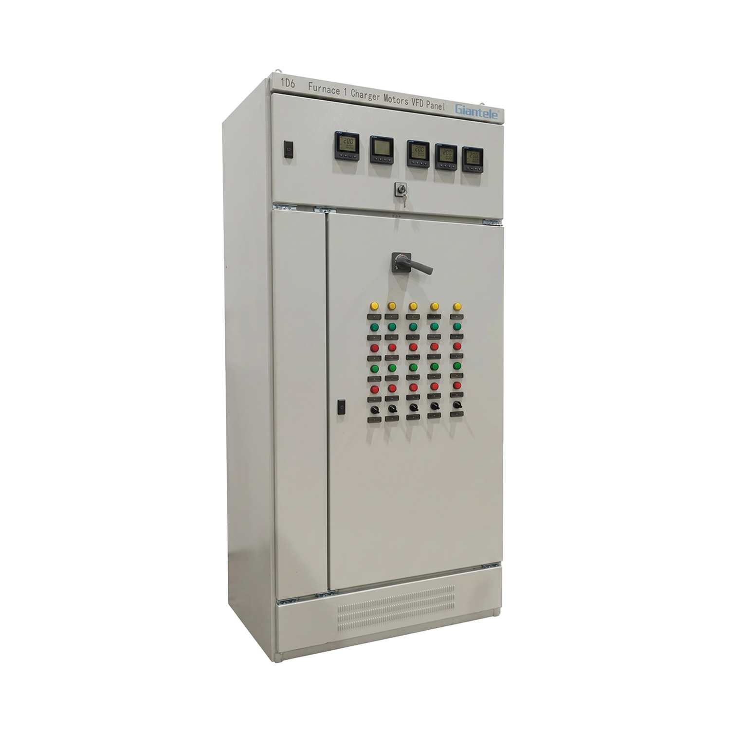
Common VFD Panel Issues and How to Prevent Them
A fault code identifies the protection function that operated, but it does not always identify the original cause. An overcurrent trip, for example, can result from unsuitable acceleration settings, damaged motor wiring, a jammed mechanical load, or incorrect motor data.
The most effective troubleshooting approach considers the incoming supply, VFD Panel, motor circuit, control system, environment, and driven equipment as one connected system.
Common Issue | Typical Symptoms | Possible Causes | Preventive Actions |
|---|---|---|---|
Overheating | Thermal trips, hot enclosure, fan noise, reduced output | Blocked filters, failed fans, dirty heatsinks, high ambient temperature, poor airflow | Clean cooling paths, inspect fans, maintain clearance, and trend cabinet temperature |
Overcurrent | Trip during starting or acceleration, unstable motion, failure to reach speed | Fast acceleration, mechanical binding, damaged cable, incorrect settings, excessive load | Check the driven machine, motor circuit, current data, and ramp settings |
Overvoltage | Trip during deceleration or sudden load reduction | Regenerative energy, short deceleration time, supply disturbance, unsuitable braking arrangement | Review deceleration requirements and inspect the braking and supply system |
Undervoltage | Random dropout, failure to start, low-voltage alarm | Supply sag, phase imbalance, loose connection, upstream switching problem | Measure the incoming supply and inspect upstream protection and terminals |
Ground fault | Trip at startup or under load, intermittent earth-fault alarms | Moisture, damaged insulation, cable abrasion, contaminated terminals | Inspect motor cables, glands, conduits, grounding, and moisture protection |
Communication fault | Lost commands, unstable reference, network errors | Loose communication cable, incorrect settings, shielding problems, interference | Inspect cable routing, shielding, connectors, and communication parameters |
Motor overload | Trip after sustained operation, high motor temperature or current | Process overload, incorrect motor data, bearing wear, blocked equipment | Confirm motor data and inspect the mechanical load |
Parameter problem | Unexpected speed, unstable control, repeated trip after adjustment | Unauthorized change, incorrect motor data, unsuitable control mode | Maintain an approved backup and document every parameter change |
Overheating and Restricted Ventilation
Overheating is often a gradual VFD Panel problem. Filters become loaded, fan output declines, oil mist coats cooling surfaces, and cabinet temperatures rise slowly. The drive may continue operating normally until peak production demand or warmer weather pushes it beyond its thermal limit.
Prevention begins with keeping the enclosure environment cool, clean, and dry. Do not store drawings, tools, spare filters, or other objects against ventilation openings. Confirm that hot exhaust air cannot return directly to the intake.
Temperature readings should be recorded under comparable loading conditions. A gradual rise at the same motor current can indicate reduced airflow, contaminated heatsinks, fan deterioration, or changing room conditions before a thermal trip occurs.
Loose Connections and Localized Heating
Vibration, repeated thermal cycling, unsuitable installation, and previous maintenance can affect electrical connections. Warning signs include heat discoloration, damaged insulation, cracked terminal blocks, corrosion, and an odor associated with overheated materials.
Connections must only be checked during an approved shutdown and tightened according to the component documentation. Applying excessive torque can damage a terminal, while insufficient torque can increase resistance and heat.
Thermal inspection during normal operation may help identify abnormal connection temperatures, but it must be carried out under the facility’s approved electrical safety procedure. Any unusual result should be compared with load current, similar phases, neighboring components, and previous inspection records.
Supply Voltage Disturbances
An unstable incoming supply can produce symptoms that resemble an internal VFD Panel failure. Voltage sags may appear when large equipment starts elsewhere in the facility, while loose upstream connections can cause intermittent undervoltage alarms.
Record voltage conditions across phases and note whether faults correspond with upstream switching events or production changes. Replacing a drive without evaluating the incoming system can leave the original problem unresolved.
Overvoltage trips during rapid deceleration require a different investigation. The motor can return energy to the DC bus as the load slows. The correct response may involve reviewing the deceleration profile, process inertia, and installed braking arrangement rather than simply increasing protection limits.
Incorrect Parameters and Changing Loads
Parameter changes should never be the first response to a recurring trip. Increasing current limits or extending protection thresholds may hide the symptom while exposing the motor or driven equipment to additional stress.
Compare the active settings with the approved backup, motor nameplate information, commissioning records, and current process requirements. Confirm acceleration time, deceleration time, maximum frequency, motor current, control mode, and overload settings.
Process conditions also change. A pump may begin handling a more viscous liquid, a conveyor may carry heavier material, or a fan may develop mechanical buildup. In these cases, the VFD Panel alarm may be evidence of a mechanical or process problem rather than an internal drive defect.
Moisture and Corrosion
Moisture can enter through damaged door seals, unsealed cable openings, conduits, unsuitable cooling arrangements, or condensation caused by temperature changes. It can contribute to corrosion, insulation failure, communication errors, and intermittent ground faults.
Inspect cable glands, enclosure seals, unused openings, conduits, and signs of water tracking. Wet electrical equipment should not be energized or touched. The moisture source must be corrected, and the affected equipment must be assessed under the approved maintenance procedure before operation resumes.
Troubleshoot a VFD Panel in a Logical Sequence
Begin by recording the complete fault code and the circumstances surrounding it. Note whether the VFD Panel trips during startup, acceleration, steady operation, deceleration, or a specific process event. Review the fault history before clearing alarms because repeated resets may remove useful evidence.
Next, inspect the system externally. Look for blocked ventilation, water exposure, damaged cables, unusual noise, burning odor, or problems with the driven machine. A seized bearing, blocked pump, misaligned coupling, or jammed conveyor can create an electrical fault even when the drive is operating correctly.
After safe isolation, divide the investigation into four areas:
Incoming supply: Check phase condition, voltage stability, protection devices, and upstream connections.
Panel and drive: Inspect cooling, terminals, internal contamination, parameters, fault history, and visible component condition.
Motor circuit: Examine motor cables, glands, grounding, terminal connections, and insulation condition using a method suitable for the connected equipment.
Mechanical load: Check bearings, alignment, blockage, process demand, and changes in operating conditions.
Correct one verified cause at a time. Replacing multiple components and changing several parameters simultaneously makes it difficult to determine what solved the problem.
After corrective work, restore all guards and covers, remove tools, and follow the approved re-energization procedure. Run a controlled test through the required speed and load range. Confirm that current, temperature, acceleration, motor direction, speed stability, and process performance remain normal.
A successful restart does not complete the investigation. Record the repair and arrange a follow-up inspection when the fault involved heat, moisture, insulation damage, or an intermittent connection.
Use Maintenance Records to Improve Long-Term Reliability
A useful VFD Panel maintenance file should include drawings, motor data, the approved parameter backup, commissioning measurements, fault history, inspection findings, component replacements, and process changes.
Avoid vague entries such as “panel checked.” Record measurable information, including output current, cabinet temperature, filter condition, fault codes, fan noise, connection condition, and the exact work completed. Consistent records allow maintenance teams to identify gradual changes that may not be obvious during a single inspection.
Spare-parts planning should reflect process criticality and replacement lead time. Filters, cooling fans, fuses, contactors, control-power devices, and communication accessories may justify planned stock, but every replacement must be verified against the installed bill of materials.
System architecture also affects maintainability. A Motor Control Center can centralize multiple motor feeders and associated control functions in one coordinated assembly. In broader low-voltage distribution systems, Withdrawable LV Switchgear can provide removable functional units that support isolation and component replacement when the installation is designed for that operating method.
Maintenance findings should also influence future panel specifications. Repeated filter blockage may justify a different enclosure or cooling approach. Persistent condensation may require improved environmental control. Difficult cable access, limited internal space, or unclear labeling should be documented so future VFD Panel projects are easier to inspect and maintain.
Conclusion
Reliable VFD Panel operation depends on controlling heat, contamination, moisture, connection condition, parameter changes, and mechanical loading before they cause repeated trips. Safe isolation, measurable inspection records, and root-cause troubleshooting are more effective than repeated resets or unnecessary component replacement.
Zhejiang Zhegui Electric Co., Ltd. is a manufacturer of low- and medium-voltage power distribution equipment. Its VFD Panel and related motor-control products can support maintainable installations when panel configuration, operating environment, cooling, inspection frequency, and documentation are matched to the application.
FAQ
Q: How often should a VFD Panel be maintained?
The interval depends on dust, humidity, temperature, operating hours, load criticality, and equipment documentation. Monthly cooling checks and scheduled shutdown inspections provide a practical starting point.
Q: What commonly causes a VFD Panel to overheat?
Typical causes include blocked filters, failed fans, contaminated heatsinks, insufficient ventilation clearance, recirculated hot air, high ambient temperature, and sustained heavy loading.
Q: Can compressed air be used to clean the cabinet?
Use it only when permitted by the equipment documentation. Uncontrolled air can spread conductive dust or force contamination deeper into terminals, heatsinks, and electronic components.
Q: Why does a drive repeatedly trip on overcurrent?
Possible causes include rapid acceleration, mechanical binding, excessive process load, damaged motor cables, incorrect motor data, unsuitable settings, or a drive that is not matched to demand.
Q: Should technicians reset a recurring fault immediately?
No. Record the code and operating conditions, identify the electrical, environmental, configuration, or mechanical cause, and correct it before returning the equipment to normal service.