


Introduction
In modern power systems, capacitor banks play a vital role in improving power factor, enhancing voltage stability, and increasing system efficiency. However, their integration into electrical networks must be handled carefully, as improper design or resonance interactions with system harmonics can introduce severe operational problems. The relationship between capacitor banks and harmonic distortion or resonance is complex and multifaceted, requiring both theoretical understanding and practical mitigation strategies. This article explores how capacitor banks can cause harmonic distortion or resonance issues, the mechanisms behind these phenomena, and the best engineering practices to prevent or manage them.
Understanding How Capacitor Banks Interact with Power Systems
A capacitor bank is a group of capacitors connected in series or parallel, used primarily for power factor correction and voltage regulation in AC electrical systems. By providing reactive power, capacitor banks reduce the reactive current drawn from the utility, thereby lowering energy losses and improving overall system efficiency.
However, the addition of capacitors changes the system’s impedance characteristics. While this is beneficial for reactive power compensation, it also alters the natural frequency of the network. When the modified natural frequency coincides with one of the existing harmonic frequencies—typically generated by nonlinear loads—resonance conditions may occur. This interaction can amplify specific harmonic currents or voltages, leading to distortion, overheating, and potential equipment damage.
The Source of Harmonics in Electrical Networks
Harmonics are voltage or current waveforms that deviate from the fundamental 50 or 60 Hz frequency due to nonlinear electrical loads. Common sources include variable frequency drives (VFDs), rectifiers, arc furnaces, fluorescent lighting, and modern electronic devices. These loads inject harmonic currents into the system, which interact with its impedance to produce voltage harmonics.
| Common Source of Harmonics | Typical Harmonic Order | Impact on System |
|---|---|---|
| Variable Frequency Drives (VFDs) | 5th, 7th, 11th, 13th | Heating of motors and transformers |
| Arc Furnaces | 2nd–25th | Severe voltage distortion |
| Computers and Office Equipment | 3rd, 5th | Increased neutral currents |
| UPS Systems | 5th–13th | Reduced power factor |
When capacitor banks are introduced into such systems, their capacitive reactance interacts with the inductive reactance of the network. This combination can lead to parallel or series resonance conditions that amplify harmonic currents.
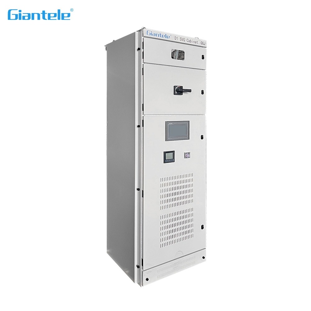
How Capacitor Banks Contribute to Harmonic Resonance
When a capacitor bank is connected to an electrical network, it forms an LC circuit with the inductance of transformers, cables, and other system components. Every LC circuit has a natural resonant frequency determined by the formula:
fr=12πLCf_r = \frac{1}{2\pi\sqrt{LC}}fr=2πLC1
If this resonant frequency coincides with one of the harmonic frequencies present in the system, resonance will occur. Two types of resonance can result:
Series Resonance: Occurs when the series impedance of inductance and capacitance is minimized, leading to excessive current flow at the resonant frequency.
Parallel Resonance: Occurs when the total impedance becomes very high, resulting in voltage amplification across the capacitor bank.
In both cases, the outcomes are undesirable. Amplified harmonic voltages can lead to equipment insulation stress, premature capacitor failure, nuisance tripping of circuit breakers, and transformer overheating.
| Resonance Type | Electrical Effect | Typical Consequences |
|---|---|---|
| Series Resonance | High harmonic current | Cable overheating, fuse blowing |
| Parallel Resonance | High harmonic voltage | Insulation stress, capacitor damage |
Real-World Impacts of Harmonic Distortion in Capacitor Banks
The practical effects of harmonic distortion due to capacitor banks can be severe and costly. The most common problems include:
Capacitor Failure: Excessive harmonic current causes overheating and dielectric breakdown of capacitor elements.
Transformer Overload: Increased harmonic currents lead to higher eddy current losses, reducing transformer lifespan.
Protective Device Malfunction: Circuit breakers and fuses may trip unnecessarily due to distorted waveforms.
Voltage Regulation Issues: Amplified harmonic voltages distort supply voltage, affecting sensitive electronic equipment.
Energy Losses: Harmonic distortion increases total RMS current, which in turn raises I²R losses in conductors.
In industrial environments with a high density of nonlinear loads, these problems are more pronounced. Engineers must therefore evaluate the harmonic profile of the system before installing or modifying capacitor banks.
Identifying Resonance and Harmonic Distortion Risks Before Installation
A key preventive measure is harmonic analysis during the design phase. Engineers should perform a frequency scan analysis to determine whether the capacitor bank’s resonant frequency aligns with the harmonic spectrum of the system.
Steps in Harmonic Risk Evaluation:
Measure existing harmonic distortion using power quality analyzers.
Model the electrical network including transformer impedance, line inductance, and load profiles.
Simulate capacitor bank addition to observe shifts in resonant frequencies.
Compare resonant frequencies with dominant harmonic orders (e.g., 5th, 7th, 11th).
Select mitigation measures if resonance risk is detected.
| Harmonic Order | Typical Frequency (60 Hz System) | Resonance Risk Level |
|---|---|---|
| 3rd | 180 Hz | Low–Moderate |
| 5th | 300 Hz | High |
| 7th | 420 Hz | High |
| 11th | 660 Hz | Moderate |
| 13th | 780 Hz | Low–Moderate |
If analysis reveals that resonance may occur near the 5th or 7th harmonic, detuned or filtered capacitor banks should be considered to shift the resonance frequency away from these harmonics.
Mitigation Techniques to Prevent Harmonic Resonance in Capacitor Banks
Several engineering strategies can be employed to prevent or minimize resonance and harmonic distortion associated with capacitor banks:
1. Detuned Reactor (De-tuned Filter)
Adding a reactor in series with the capacitor bank shifts its resonant frequency below the lowest harmonic frequency (typically below the 5th). This prevents harmonic amplification while still providing reactive power support.
2. Tuned Harmonic Filters
These filters are designed to absorb specific harmonics by tuning to a particular frequency, such as the 5th or 7th harmonic. They offer targeted mitigation for systems with known harmonic orders.
3. Active Power Filters (APFs)
Active filters inject compensating currents in real-time to cancel harmonic components. Though costlier, they provide dynamic and adaptable harmonic control, especially in variable-load environments.
4. Hybrid Filtering Solutions
Combining passive (detuned) and active filters provides a balanced approach—achieving both harmonic mitigation and reactive compensation.
5. Capacitor Bank Segmentation
Dividing a large capacitor bank into smaller steps, each with separate switching control, allows better load matching and reduces resonance potential when load profiles change.
Engineering Design Best Practices for Capacitor Bank Integration
Effective design and installation of capacitor banks can prevent most resonance and harmonic issues. The following guidelines are widely recognized in power system engineering:
Conduct thorough harmonic analysis before installation or expansion.
Use detuned reactors with tuning frequencies around 189 Hz (for 50 Hz systems) or 227 Hz (for 60 Hz systems).
Install capacitor banks near major inductive loads rather than at the main distribution bus to localize resonance effects.
Avoid oversizing capacitor banks, as excessive reactive power increases harmonic vulnerability.
Regularly monitor power quality using harmonic analyzers to detect early signs of resonance or capacitor degradation.
Follow IEEE 519 and IEC 61000 standards, which specify acceptable harmonic limits and mitigation practices.
These principles ensure long-term system reliability while maintaining efficient reactive power management.
The Economic Impact of Ignoring Harmonic Distortion
Failing to address harmonic resonance caused by capacitor banks can lead to substantial financial losses. Repeated equipment failures, reduced transformer efficiency, and unscheduled downtime all contribute to rising operational costs. Moreover, some utility providers impose penalties for excessive harmonic distortion, adding a financial incentive for proper management.
| Cost Factor | Short-Term Impact | Long-Term Consequence |
|---|---|---|
| Equipment Replacement | High upfront cost | Reduced ROI |
| Energy Losses | Increased electricity bill | Ongoing operational inefficiency |
| Unplanned Downtime | Production losses | Customer dissatisfaction |
| Utility Penalties | Financial fines | Reputational damage |
A well-designed capacitor bank system with proper filtering ensures not only technical stability but also economic sustainability.
Conclusion
Capacitor banks are essential for optimizing power factor and improving voltage stability, but they must be carefully designed and integrated to avoid harmonic distortion and resonance issues. The interplay between system inductance and capacitance can lead to unwanted amplification of harmonic frequencies, causing overheating, equipment failure, and power quality degradation. Through careful harmonic analysis, detuned filtering, and adherence to engineering standards, these challenges can be effectively mitigated. Properly managed, capacitor banks remain one of the most valuable tools in modern electrical power systems—balancing efficiency with reliability.
FAQ
1. Why do capacitor banks cause resonance?
Because capacitor banks alter the system’s impedance characteristics, they can create resonance with system inductance at specific harmonic frequencies.
2. Can harmonic filters completely eliminate resonance issues?
No. They significantly reduce the risk, but system configuration and load variations can still influence resonance conditions. Regular monitoring is essential.
3. How can I identify if my system is experiencing harmonic distortion due to capacitor banks?
Symptoms include capacitor overheating, nuisance breaker trips, transformer noise, or distorted voltage waveforms visible on harmonic analyzers.
4. What is the best type of capacitor bank for harmonic-rich environments?
Detuned or filtered capacitor banks are most suitable since they shift or absorb harmonics instead of amplifying them.
5. Are there international standards governing harmonic limits?
Yes. IEEE Std 519 and IEC 61000 define acceptable harmonic distortion limits and provide guidance for mitigation techniques.