
I. Definition: The Reactive Power Solution
A capacitor bank (often called a SVG Active Static Var Generator) is a crucial device for optimizing power supplies and overall electrical system efficiency. Manufactured to the stringent International Electrotechnical Commission standard IEC 62271, it consists of multiple capacitor units, reactors, controllers, and protective devices (fuses, circuit breakers).
Its primary function? Reactive Power Compensation. Capacitor banks store electrical energy in an electrostatic field and release it back into the electrical system as needed. By connecting these units in parallel with the electrical supply, the bank injects "leading" reactive power (kVar). This directly counteracts the "lagging" reactive power inherently drawn by inductive loads (like motors and transformers), thereby:
II. Why Use Capacitor Banks? Key Benefits for Your Supply & System
Low power factor has significant detrimental effects. Understanding the difference between Real Power (P) and Reactive Power (Q) is important.
Real Power is the useful energy that equipment uses. Reactive Power is the energy needed to create magnetic fields. However, Reactive Power is not used directly for work. Capacitor banks correct this imbalance, offering substantial advantages:
Reduces Required Electrical Supply Capacity & Cost:
By improving cos φ from (e.g.) 0.8 to 0.95, the need for expensive generation, transmission lines, and substation equipment capacity is reduced. Installing capacitors frees up existing capacity.
Lowers Electricity Bills & Energy Losses:
Higher power factor translates directly to reduced wasted electrical energy and lower utility costs. Less energy is lost as heat across the electrical system.
Maximizes Existing Power Supply Capacity:
Correcting power factor allows your current electrical supply infrastructure to deliver more usable real power (kW) without needing immediate upgrades to transmission lines or transformers.
Improves Voltage Stability & Extends Equipment Life:
Stabilizing voltage levels reduces stress on sensitive equipment connected to your power supplies.
Avoids Utility Penalties:
Many utilities charge fees for facilities operating with a chronically low power factor. Capacitor banks prevent these costly penalties.
Mitigates Harmonics:
When combined with detuning reactors, capacitor banks are essential protection against damaging harmonic distortion, especially crucial in electrical systems with non-linear loads like:
VFDs, Pumps, Large Motors
Industrial Machinery (Welding, Rolling Mills)
HVAC Systems
Data Centers (UPS, SMPS)
Renewable Energy Inverters (Solar PV, Wind)
EV Charging Stations
And etc.

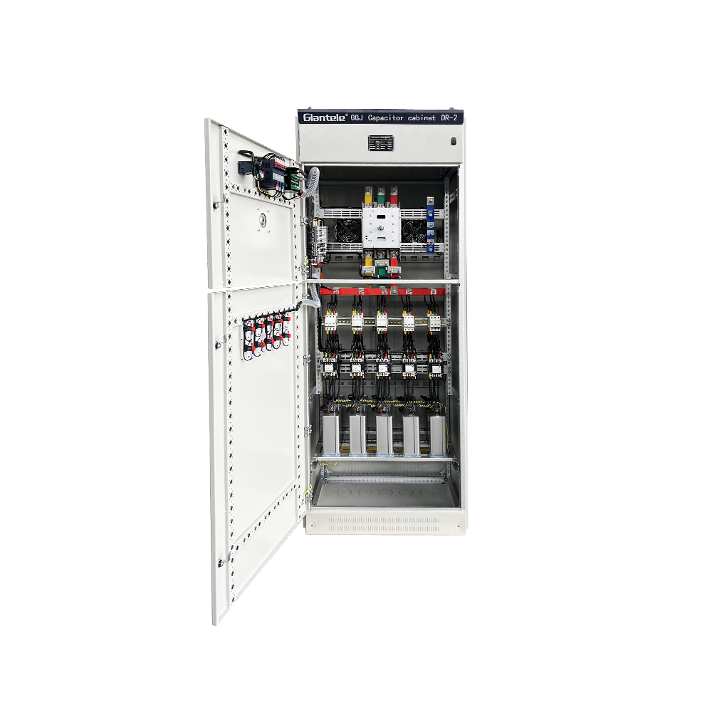
Capacitor Bank Inside

Components of Capacitor Bank

Capacitor Bank
III. Where to Install Capacitor Banks in the Electrical System?
The optimal placement depends on the system's needs:
1.Centralized Compensation:
Banks installed at main substations (HV/LV level) serving large sections of the electrical system.
2.Group Compensation:
Banks placed at distribution transformers or major plant distribution panels.
3.Local Compensation:
Capacitors connected directly at individual large motors or inductive loads, providing the most targeted correction.
IV. Common Failures: Protecting Your Investment
Capacitor banks operate in demanding environments. Understanding common failure points aids in prevention:
1.Capacitor Unit Failures:
Case Bulging/Damage: Caused by overheating or corrosive environments impacting the components storing stored energy.
Rupture/Explosion: Severe overvoltage (e.g., switching surges) or internal dielectric faults releasing stored energy catastrophically
2.Contactor Failures (Used for Switching Banks):
Contact Welding: Often due to excessive inrush currents caused by: switching too rapidly (< 30s discharge time) - leading to voltage spikes on residual stored energy - or high harmonic distortion.
Mechanical Wear: Frequent switching operations lead to physical degradation.
V. Safe Operation
Proper handling ensures longevity and safety:
1.Switching Sequence is Critical:
Shutdown: Disconnect capacitor banks before other loads/breakers.
Startup: Energize capacitor banks only after the main electrical supply is stable and other loads are running. Never close breakers onto banks immediately after a grid blackout.
2.Switching Intervals:
Automatic controllers handle switching, but ensure MINIMUM 30 seconds (ideally 60+ seconds) between operations to allow internal discharge of stored energy. Absolutely never close onto a capacitor bank known to hold a residual charge.
3.Responding to Protection Device Trips:
Strict Prohibition: Immediately reclosing a capacitor breaker or contactor after an automatic trip (lockout) is strictly prohibited.
Mandatory Investigation: The cause of the trip must be thoroughly investigated and identified before any reclosure attempt.
Analysis Procedure: Examine controller event logs, protective relay flags/targets, and relevant monitoring equipment.
Physical Inspection: Visually inspect capacitor units, switching contactors, fuses, associated cabling, connections, and control circuitry for any signs of damage, overheating, or malfunction.
Re-energization Protocol: The capacitor bank may only be re-energized after the root cause of the trip has been conclusively determined and the fault condition has been rectified.
4.Mandatory Safety Discharge (Before ANY Work):
Internal discharge resistors are NOT sufficient for safety. Always perform a visible earth discharge: Use an insulated, rated discharge stick to short capacitor terminals to ground and to each other multiple times. Verify the absence of voltage using a capacitor-rated voltmeter.
VI. Routine Maintenance Schedule:
Temperature Control:
Maintain ambient temperatures below 40°C wherever banks are located.
Regular Cleaning:
Remove dust and contaminants from bushings, insulators, casings, and reactors. Buildup can cause tracking or overheating.
Quarterly Inspections (During Outages):
Check discharge resistors/VTs, terminal integrity, grounding, and overall condition. Perform insulation resistance (IR) and Tan δ tests if possible.
Documentation:
Keep detailed logs of all inspections, tests, and maintenance actions.
VII. Conclusion: Essential for Modern Power Systems
Capacitor banks are indispensable for the efficient, stable, and cost-effective operation of modern electrical systems. By dynamically supplying reactive power, they correct low power factor issues at the source. This delivers significant benefits:
Reduced electrical energy losses on transmission lines and throughout the distribution network (lower I²R losses).
Minimized voltage drops and enhanced stability for better quality power supplies.
Avoidance of costly utility penalties.
Maximized utilization of existing electrical supply capacity (generation, transmission lines, transformers), potentially delaying expensive upgrades.
Extended lifespan for sensitive equipment.
To ensure optimal performance and safety, capacitor banks require correct selection based on system needs (especially harmonic levels), installation compliant with standards like IEC 62271, strict adherence to switching protocols, rigorous discharge procedures when handling stored energy, and a disciplined preventative maintenance regimen. Properly implemented, capacitor banks are a vital investment in optimizing your power infrastructure.