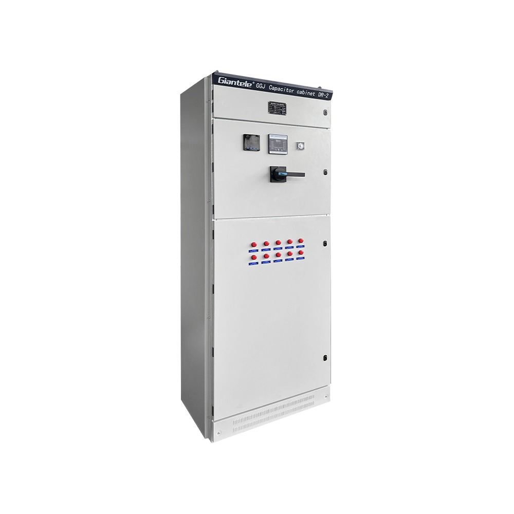


Capacitor banks are essential components in modern electrical power systems, used to improve power factor, stabilize voltage, and enhance overall energy efficiency. In industrial plants, commercial facilities, and utility networks, they play a key role in reducing reactive power losses and maintaining reliable system operation. However, like all electrical assets, capacitor banks degrade over time due to stress, overvoltage, harmonic distortion, and environmental factors. Regular testing of a capacitor bank is vital to assess its health, detect early signs of deterioration, and maintain optimal performance. A systematic approach to capacitor bank testing not only prevents unplanned downtime but also extends equipment lifespan and ensures electrical safety.
Testing a capacitor bank is not simply a routine maintenance task—it’s an essential part of preventive electrical asset management. The primary goal is to ensure the bank operates within design specifications and continues to deliver reactive power compensation efficiently.
Capacitor banks can fail due to aging, dielectric breakdown, loose connections, or excessive harmonics. Such issues can lead to reduced reactive power, voltage fluctuations, or even catastrophic failure. Testing helps identify the specific condition of each capacitor unit, detect imbalance between phases, and confirm that the bank’s control and protection systems are functioning properly.
| Purpose of Testing | Key Benefits |
|---|---|
| Identify failing capacitors | Prevents power factor degradation |
| Ensure balanced performance | Reduces stress on the power system |
| Validate protection and control circuits | Enhances operational safety |
| Monitor dielectric health | Extends equipment lifespan |
By understanding the purpose behind each test, engineers can design a proactive maintenance schedule that targets performance optimization and risk mitigation.

To accurately assess a capacitor bank’s health and performance, technicians must focus on specific electrical and physical parameters. Each of these indicators reveals valuable insights about the condition of the system.
Capacitance determines the reactive power output of the bank. Deviations from the rated capacitance indicate internal deterioration, such as insulation breakdown or plate damage.
The dissipation factor measures dielectric losses within the capacitor. A higher value suggests insulation contamination, aging, or moisture ingress.
This parameter measures the integrity of insulation between terminals and the grounded frame. Low insulation resistance points to potential leakage or contamination.
Balanced phase voltages and currents are essential for even reactive power distribution. Any imbalance could indicate a failed unit or poor connection.
| Parameter | Ideal Range / Condition | Indication of Problem |
|---|---|---|
| Capacitance | Within ±5% of rated value | Reduced reactive power |
| Dissipation Factor | Below 0.5% | Aging dielectric |
| Insulation Resistance | >1000 MΩ | Moisture or leakage |
| Voltage/Current Balance | ±2% between phases | Faulty unit or wiring |
By systematically measuring these parameters, a clear picture of the capacitor bank’s health can be established.
Before conducting any form of testing, safety should be the top priority. Capacitor banks can store significant electrical energy even after disconnection from the supply, posing severe shock and arc flash risks. Proper safety procedures are non-negotiable.
Isolate the bank: Disconnect it from all power sources using lockout-tagout (LOTO) procedures.
Discharge stored energy: Use appropriate discharge resistors to safely drain residual charge.
Verify zero voltage: Confirm with an approved voltage tester that no residual voltage remains.
Use PPE: Wear arc-rated gloves, face shields, and insulating mats.
Follow manufacturer guidelines: Each bank may have specific discharging and testing instructions.
Neglecting safety not only endangers personnel but can also damage the testing instruments and capacitor units themselves.
Testing a capacitor bank requires a structured, multi-stage approach. Each stage assesses different performance and reliability aspects.
Begin with a thorough visual check of the capacitor bank, including all busbars, terminals, and fuses. Look for signs of bulging, oil leakage, corrosion, or burnt marks on capacitor cans and cables. Visual symptoms often indicate internal faults or overheating.
Use a digital capacitance meter to measure each unit’s capacitance. Compare readings with the rated nameplate values. A deviation beyond ±5% usually indicates deterioration.
Perform insulation resistance testing using a 500V or 1000V megohmmeter. Measure between terminals and between terminal to ground. Readings below 1000 MΩ suggest contamination or insulation breakdown.
This test evaluates dielectric losses using a Tan Delta test set. Compare the measured dissipation factor to standard reference values—an increasing trend over time suggests progressive dielectric aging.
With the capacitor bank energized, measure phase voltages and currents using a clamp meter or power analyzer. Any imbalance indicates a failed unit or unbalanced load conditions.
Use a power quality analyzer to identify harmonic distortion. Excessive harmonics can overheat capacitors and reduce their lifespan.
Infrared thermography helps detect hotspots on terminals, busbars, and capacitor enclosures, revealing loose connections or overloading.
By systematically executing each step, maintenance teams can ensure accurate, reliable diagnostics of capacitor bank health.
Using the right instruments is essential to obtain precise results and maintain testing safety. Below is a summary of common testing tools used in capacitor bank diagnostics.
| Testing Tool | Purpose | Remarks |
|---|---|---|
| Capacitance Meter | Measures individual capacitor values | Use only on isolated units |
| Megohmmeter | Tests insulation resistance | 500–1000V DC recommended |
| Power Quality Analyzer | Measures voltage/current balance, harmonics | For live system analysis |
| Infrared Camera | Detects thermal hotspots | Non-contact testing method |
| Tan Delta Test Set | Assesses dielectric losses | High-accuracy laboratory testing |
Each tool serves a specific function, and combining their results gives a comprehensive evaluation of both health and performance metrics.
Once all measurements are collected, interpretation is crucial. Proper diagnosis ensures targeted corrective actions.
Low Capacitance Value: Indicates capacitor element failure or internal disconnection. Replace the affected unit.
High Dissipation Factor: Signals dielectric contamination or moisture absorption—often requires unit replacement.
Low Insulation Resistance: Suggests insulation failure or terminal contamination. Clean or replace as needed.
Unbalanced Current Flow: Likely caused by a failed capacitor unit or poor contact. Inspect fuses and connections.
Thermal Hotspots: Points to loose terminals or excessive harmonic load. Tighten and monitor regularly.
Trend analysis over multiple testing intervals provides a more reliable picture than one-time readings, helping identify degradation patterns early.
Testing should always lead to actionable maintenance strategies. A capacitor bank that passes basic testing but operates in harsh or fluctuating conditions may still require performance optimization.
Monthly: Visual inspection, temperature scanning
Quarterly: Capacitance and voltage/current balance checks
Annually: Full insulation, Tan Delta, and harmonic testing
If harmonic distortion exceeds design limits, integrate detuned reactors or harmonic filters to protect the capacitors from overloading.
Maintain optimal load conditions to prevent overvoltage or undercompensation. Continuous monitoring via SCADA or energy management systems can automate this process.
Control ambient temperature and humidity around the capacitor bank to reduce dielectric stress and prevent condensation-related failures.
Implementing these proactive steps keeps the capacitor bank operating at peak efficiency while minimizing long-term maintenance costs.

Even experienced technicians can make critical errors that compromise test accuracy or equipment safety.
Skipping the Discharge Process: Residual charge can damage instruments or cause electric shock.
Testing in Energized Condition (where not applicable): Always isolate before insulation or capacitance tests.
Ignoring Small Deviations: Even minor capacitance drift or imbalance can escalate into system instability.
Using Uncalibrated Instruments: Incorrect readings can mislead diagnostics.
Neglecting Environmental Influence: Temperature and humidity significantly affect results—record these conditions during testing.
Avoiding these pitfalls ensures more reliable diagnostics and safer operations.
Regular testing of a capacitor bank is fundamental to maintaining the reliability and efficiency of any electrical distribution system. By focusing on key parameters like capacitance, insulation resistance, dissipation factor, and harmonic levels, engineers can detect early deterioration before it leads to failure. A disciplined approach—combining thorough visual inspection, precise electrical testing, and smart performance analysis—ensures that the capacitor bank continues to deliver consistent power factor correction and voltage stability. Ultimately, systematic testing not only preserves equipment health but also supports the broader goal of sustainable, efficient energy management.
1. How often should a capacitor bank be tested?
Capacitor banks should be visually inspected monthly, electrically tested quarterly, and undergo comprehensive diagnostic testing annually. However, in harsh environments or high-load systems, more frequent testing may be necessary.
2. What causes capacitor bank failure?
Common causes include overvoltage, excessive harmonics, dielectric aging, moisture ingress, and unbalanced loads. Regular testing helps detect these issues before catastrophic failure.
3. Can a failed capacitor unit affect the entire bank?
Yes. A single failed capacitor can cause voltage imbalance, overloading of remaining units, and power factor reduction. Immediate isolation or replacement is recommended.
4. What is a safe capacitance deviation range?
A deviation within ±5% of the rated capacitance is generally acceptable. Beyond that range, replacement is advised to maintain reactive power performance.
5. Are online monitoring systems effective for capacitor banks?
Yes. Modern power monitoring systems can continuously track voltage, current, temperature, and harmonics, providing early alerts that complement periodic manual testing.


